Evaporative Emissions System: Testing and Inspection
Fig. 57 Testing the purge control valve:
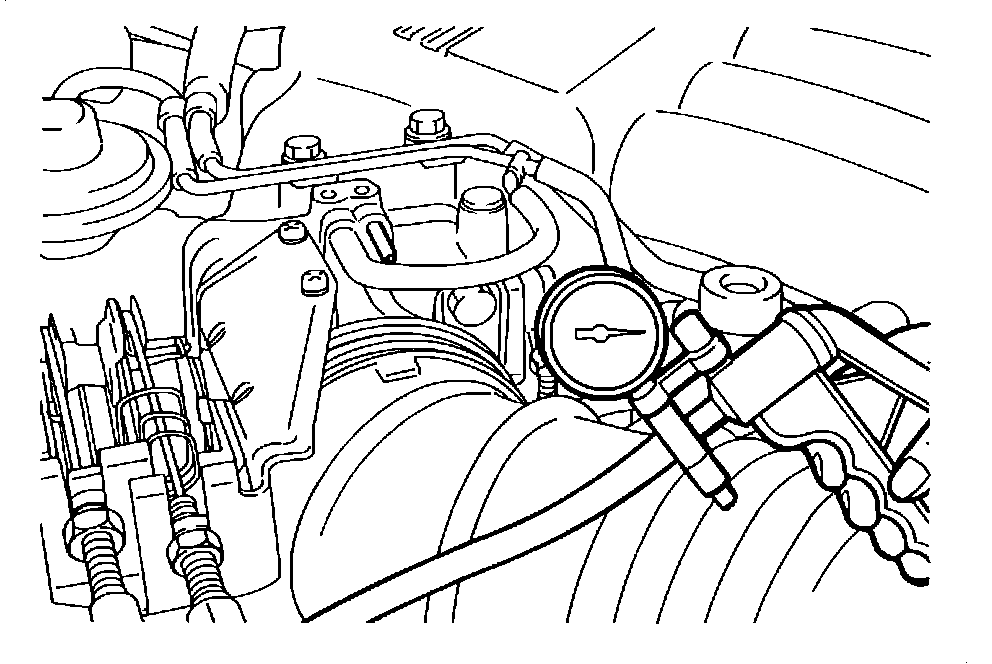
SYSTEM TESTING
1. Disconnect the vacuum hose (red stripe) from the throttle body and connect a manual vacuum pump to the hose, Fig. 57.
2. While the engine is cold (coolant temperature less than 60 degrees C or 140 degrees F) verify that when 53 kPa (15 in. Hg) of vacuum is applied while holding the engine at 2,500 rpm that vacuum can be held.
3. Allow the engine to warm up (coolant temperature greater than 70 degrees C or 158 degrees F) and verify that while the engine is idling and the air conditioner switch is on that vacuum leaks.
4. Turn the air conditioning switch off and verify that while the engine continues to idle it is possible to produce 53 kPa (15 in. Hg) of vacuum.
5. Open the throttle until the engine is running at 2,500 rpm and verify that for three minutes vacuum leaks but after three minutes of operation vacuum holds for a short period and then leaks once again.
Overfill Limiter (Two Way Valve):
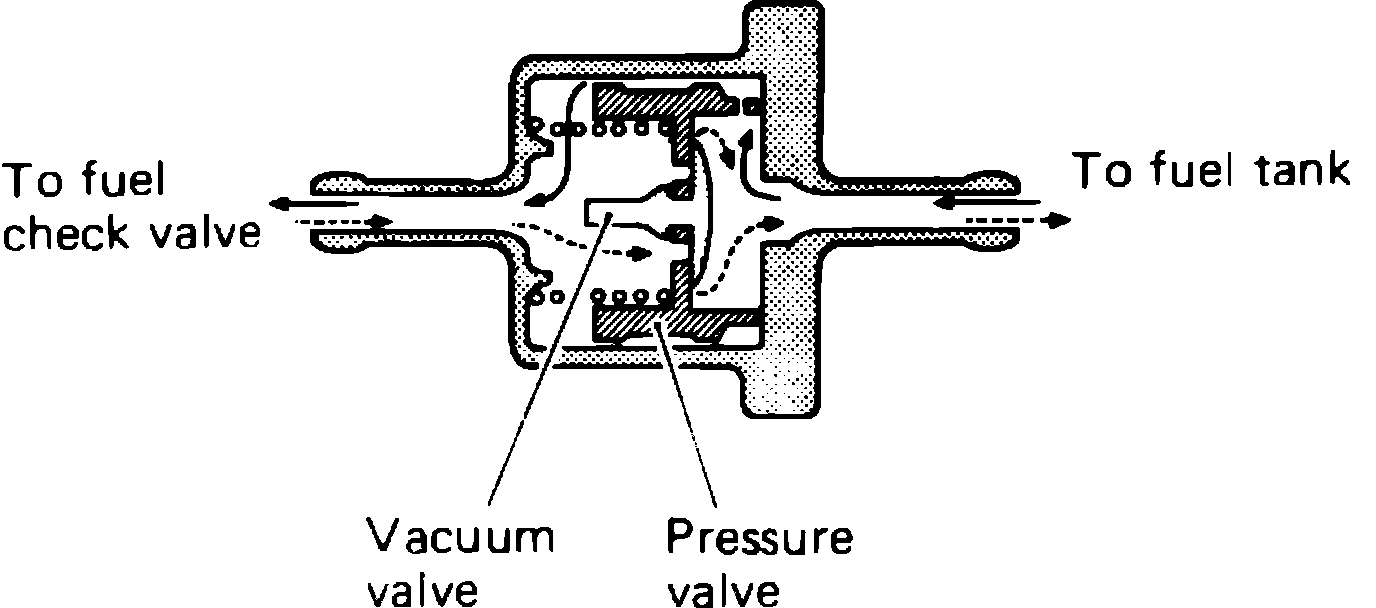
OVERFILL LIMITER VALVE
Remove the overfill limiter valve and blow gently through both ends. Air should pass through the valve in both directions with slight resistance.
PURGE CONTROL VALVE
1. With the engine warmed up to normal operating temperature and ignition key in the "OFF" position, remove the purge hose from the air cleaner and blow into it. Air should not flow through the purge control valve.
2. Start the engine and accelerate it to 2000 rpm. Blow into the hose and verify that air passes through the purge control valve.
3. If air will not pass check the operation of the thermo valve and its connecting vacuum hoses for breaks and obstructions.
Fig. 59 Testing the purge control valve:
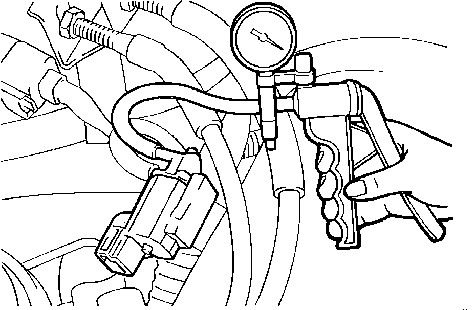
PURGE CONTROL SOLENOID VALVE
1. Mark and disconnect the vacuum hose (black with red stripe) from the solenoid valve.
2. Disconnect the electrical harness connector.
3. Connect a manual vacuum pump to the nipple the red striped hose was removed from, Fig. 59.
Fig. 60 Testing the purge control valve:
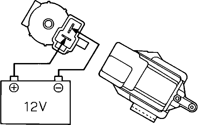
PURGE CONTROL SOLENOID VALVE
4. Attempt to apply a vacuum and verify that while voltage is applied to the solenoid valve leaks, Fig. 60.
5. Remove power from the solenoid valve and verify that the solenoid valve holds vacuum.
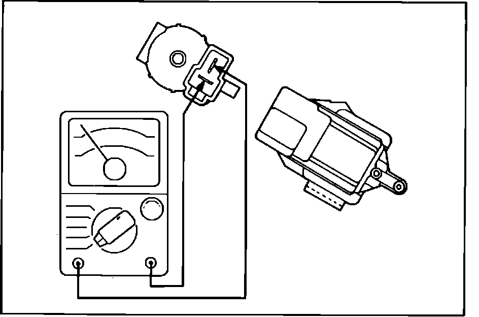
Fig. 61 Testing the purge control valve:
PURGE CONTROL SOLENOID VALVE
6. Measure the resistance between the two terminals of the solenoid valve, Fig. 61 and verify that the resistance is between 36 and 44 ohms at 20 degrees C (68 degrees F).
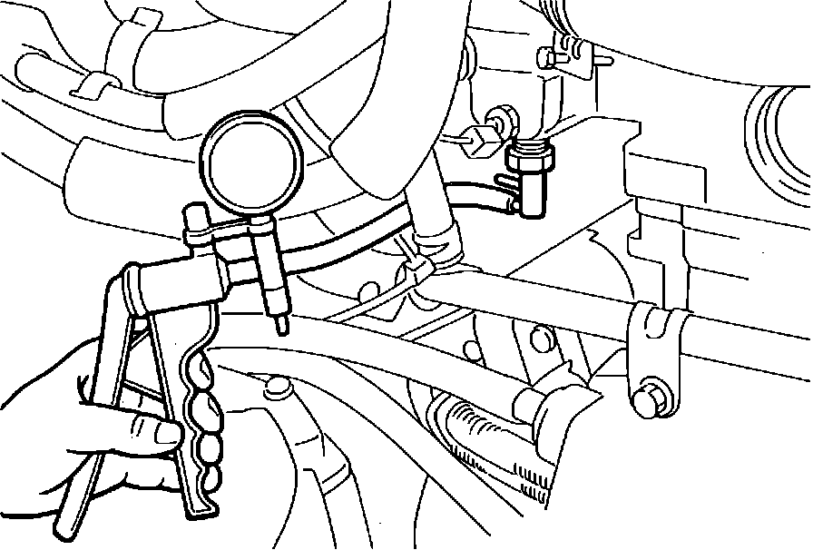
Fig. 40 Testing thermo valve:
THERMO VALVE
1. Disconnect the vacuum hoses from the thermo valve and connect a manual vacuum pump to the thermo valve, Fig. 40.
2. Apply a vacuum and verify that when engine coolant temperature is less than 50 degrees C or 122 degrees F that the thermo valve leaks.
3. Allow the engine to warm up until the coolant temperature exceeds 80 degrees C or 176 degrees F and verify that the thermo valve will hold a vacuum.
Note: If the thermo valve fails and must be replaced use 3M locking sealant 4171 or equivalent and torque the thermo valve to 20 to 40 Nm (15-30 ft. lbs.). Do not use wrenches or pliers on the resin part of the valve during installation.