Repair Procedure 1
REPAIR PROCEDURESPROCEDURE 1: RE-CALIBRATE THE AUTOMATIC CHOKE BY INSTALLING CHOKE SHIM
CARBURETOR REMOVAL IS NECESSARY FOR CHOKE SHIM INSTALLATION.
1. Remove the air cleaner.
NOTE: The engine must be cool so that the thermo-wax plunger is retracted.
2. To prevent excessive coolant leakage install locking clamp pliers on the coolant hose from the intake manifold to the choke thermo wax housing. Then twist and disconnect the hose from the carburetor.
3. Disconnect the accelerator cable and wire harness connector from the carburetor. Remove the fuel lines and hose connections.
4. Remove the four carburetor through bolts and washers.
5. Lift the carburetor off the intake manifold.
NOTE: Usually a quick, hard pull will separate the carburetor from the intake manifold. Cover the exposed intake manifold ports with a shop towel.
6. Support the carburetor. Take caution not to damage the throttle linkage that extends below the base of the carburetor.
Figure 3:
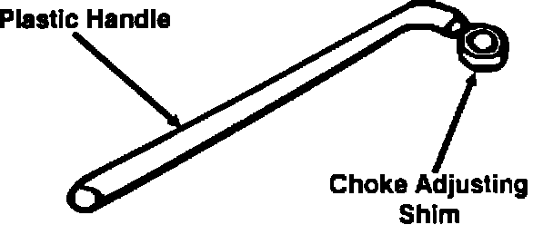
7. From Parts Kit MD162375 obtain the Choke Adjusting Shim with plastic handle. This is shown in Figure 3.
Figure 4:
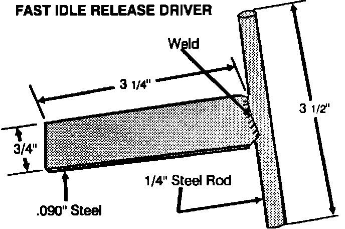
Fast Idle Release Driver was previously distributed with EMR-89-001. If your dealership does not have one, Figure 4 contains information for making one.
Figure 5:
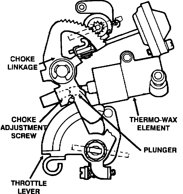
Shown in Figure 5 is a basic outline view of the choke mechanism.
Note that the area between the choke adjustment screw and the plunger is behind the choke linkage and is hidden from view.
Figure 6:
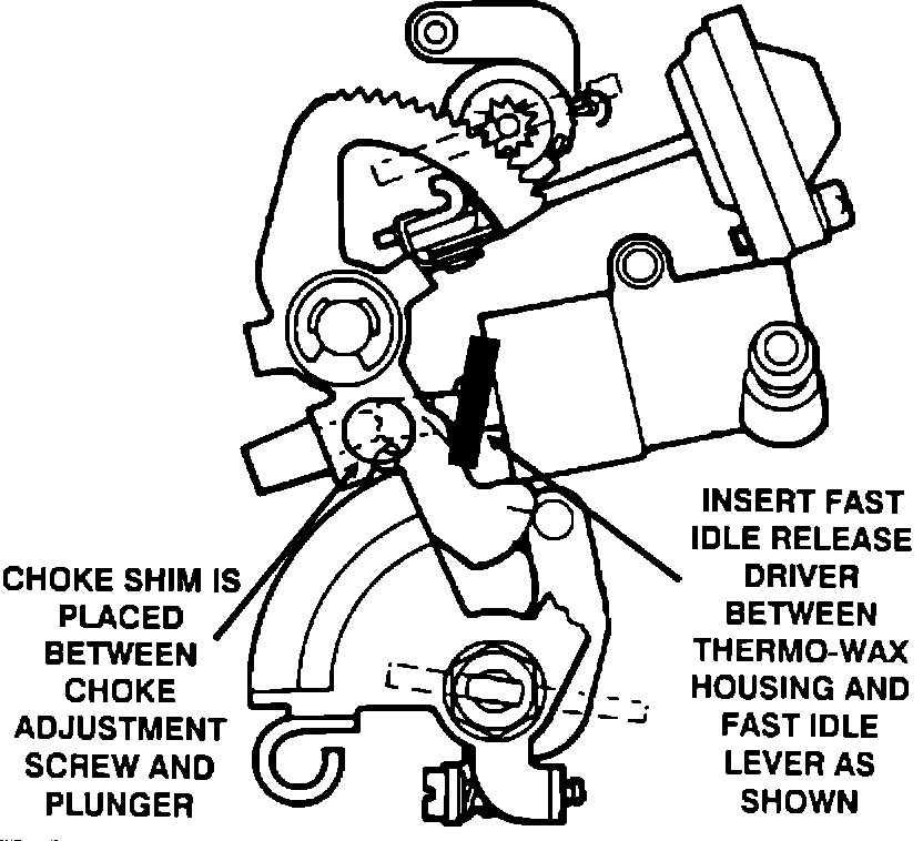
8. Using the fast idle release driver special tool, insert the tool between the thermo wax element housing and the choke linkage (Figure 6).
Figure 7:
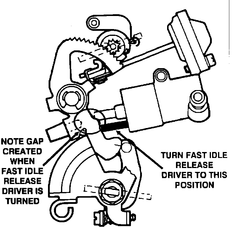
9. Spread the choke linkages to create a gap between the choke adjustment screw and the plunger of the thermo wax element. Make sure not to interfere with the throttle lever or other linkages.
Figure 8:
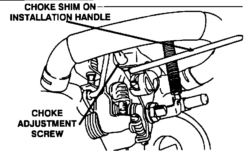
10. With the linkages spread, install the cap portion of the choke shim onto the threaded end of the choke adjustment screw. The cap portion of the shim should be inserted between the plunger and the choke adjustment screw.
Figure 9:
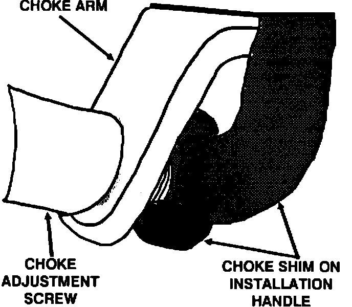
11. Put the shim over the end of the choke adjustment screw and release the linkage. Check to see that the shim is properly in place as shown in Figure 9.
Figure 10:
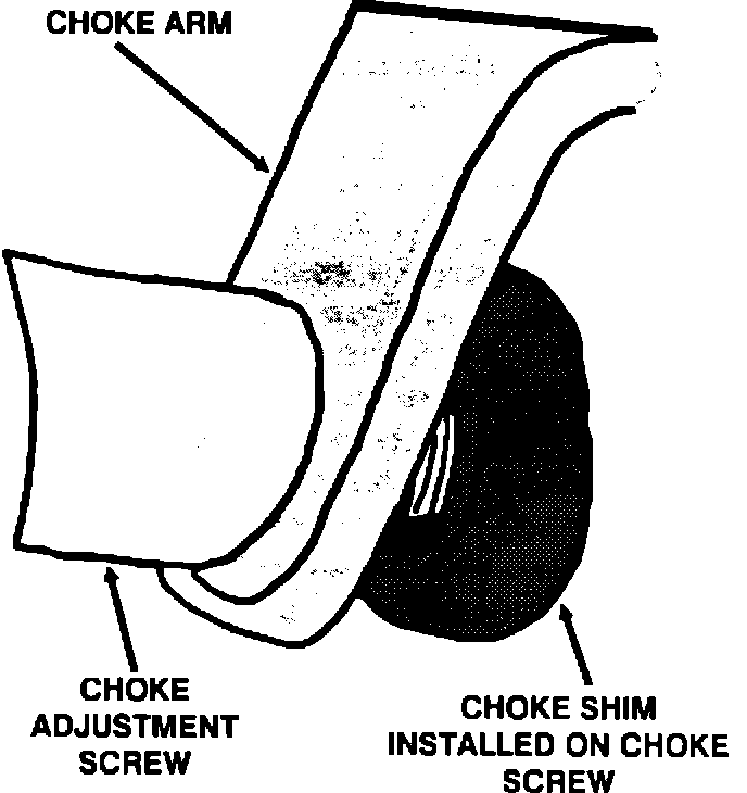
12. Twist off the plastic handle and discard it. When the installation handle has been removed from the choke shim visually inspect the installation. The choke shim should be installed as in Figure 10.
13. Reinstall the carburetor using the reverse order of the removal procedure. Use the new carburetor gasket from the service kit. Remove the locking clamp pliers from the coolant hose and check all vacuum hose routing and carburetor fastener torques.
14. Reinstall the air cleaner.