Oscilloscope Check
IGNITION COIL AND IGNITION POWER TRANSISTOR INSPECTION USING AN ANALYZERRequired Special Tool: MB991348 Test Harness
MEASUREMENT METHOD
1. Disconnect the ignition power transistor connector and connect test harness special tool, MB991348, in between. (All terminals should be connected.)
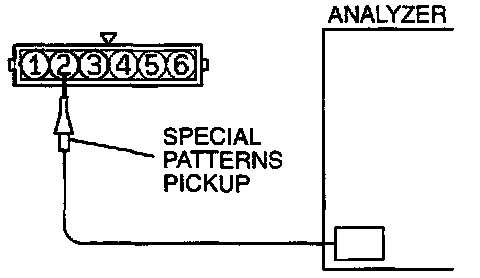
2. Connect the analyzer special patterns pickup to the ignition power transistor connector terminal to analyze each pair of cylinders:
- Terminal number 1 for the number 3 and 6 cylinders
- Terminal number 2 for the number 2 and 5 cylinders
- Terminal number 3 for the number 1 and 4 cylinders
ALTERNATE METHOD (Test harness not available)
1. Connect the analyzer special patterns pickup to ECM terminal 11. (When checking the number 1 and 4 cylinders.)
2. Connect the analyzer special patterns pickup to ECM terminal 12. (When checking the number 3 and 6 cylinders.)
3. Connect the analyzer special patterns pickup to ECM terminal 13. (When checking the number 2 and 5 cylinders.)
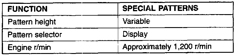
OBSERVATION CONDITIONS
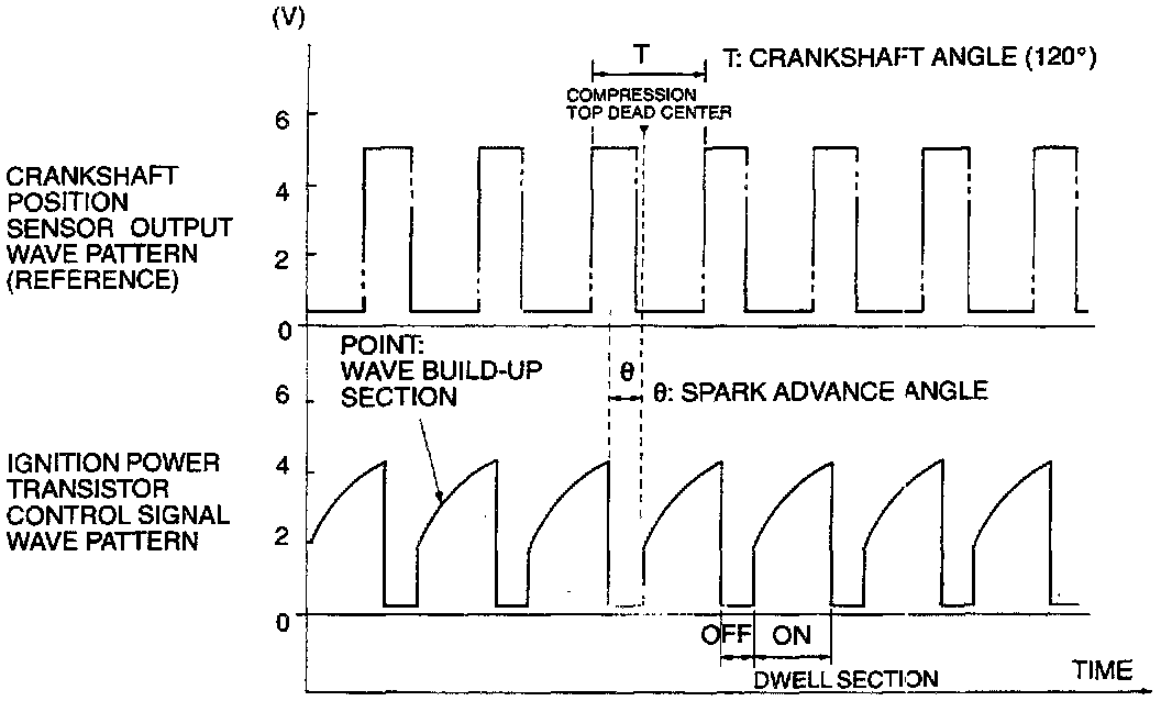
STANDARD WAVE PATTERN
Wave Pattern Observation Point
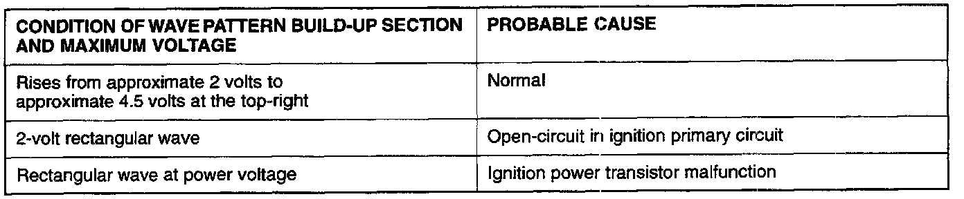
Condition of wave Pattern build-up section and maximum voltage (Refer to abnormal wave pattern examples 1 and 2).
EXAMPLES OF ABNORMAL WAVE PATTERNS
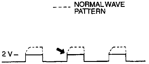
Example 1 (Wave pattern during engine cranking)
- Cause of problem
Open-circuit in ignition primary circuit
- Wave pattern characteristics
Top-right part of the build-up section cannot be seen and voltage value is approximately 2 volts too low.
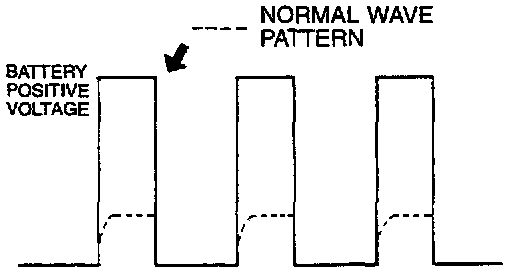
Example 2 (Wave pattern during engine cranking)
- Cause of problem
Malfunction in ignition power transistor
- Wave pattern characteristics
Power voltage results when the ignition power transistor is "ON."