Disassembly
DisassemblyComponents
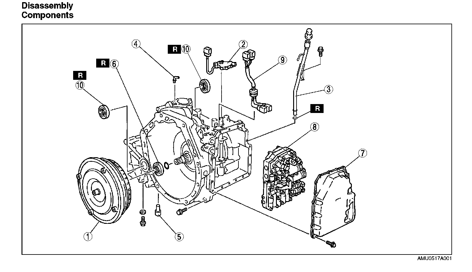

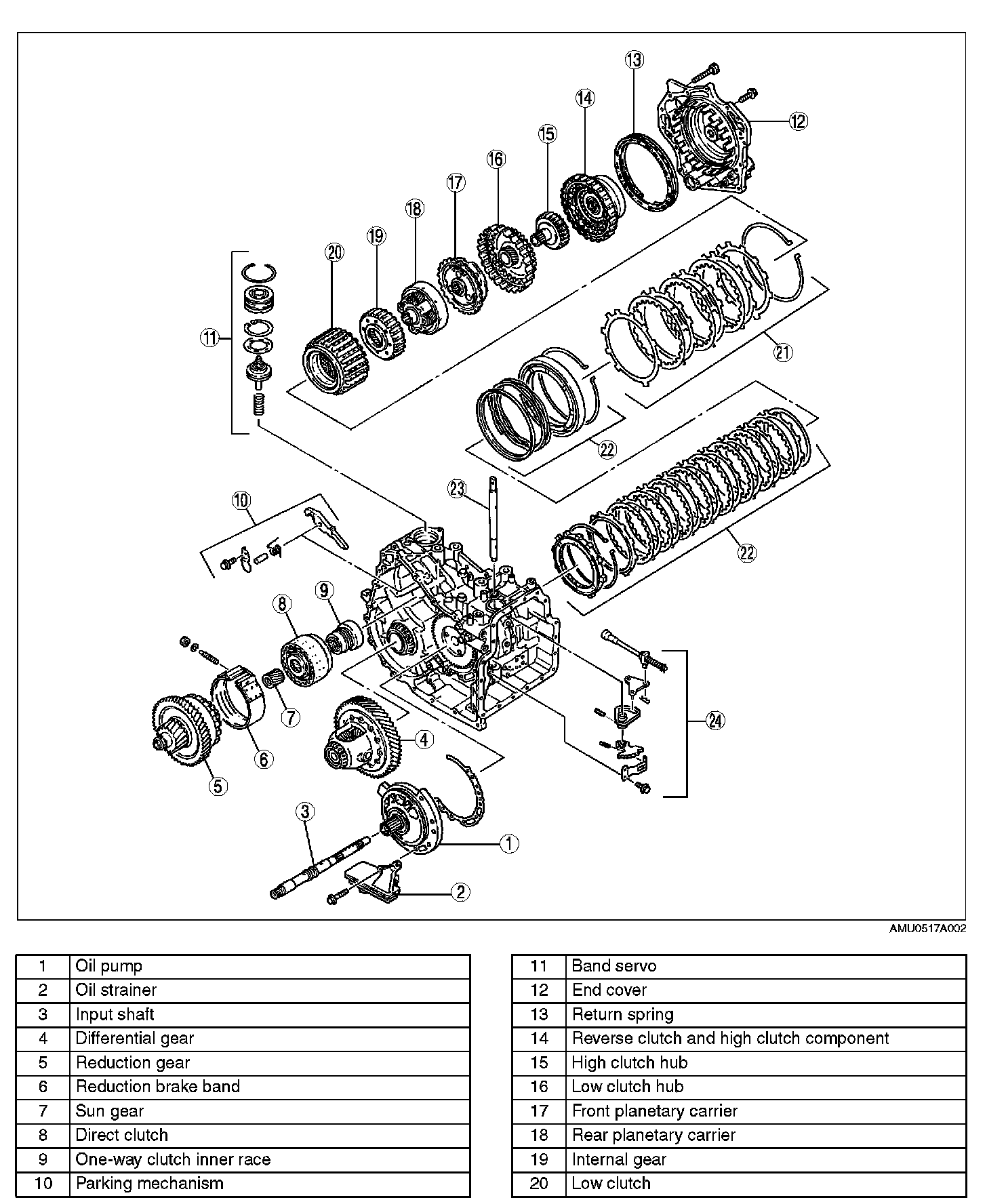

Disassembly procedure
1. Remove the torque converter, and immediately turn it so that the hole faces upward. This will help to keep any remaining fluid from spilling.
2. Remove the transaxle range switch.
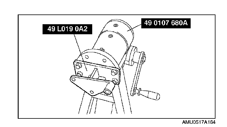
3. Set the transaxle to a transmission stand using the SST.
Caution:
^ Be careful not to scratch the mating surfaces of the control valve body cover and the transaxle case.
^ After removing the control valve body cover, remove the liquid gasket remaining on the mating surfaces.
4. Remove the control valve body cover.
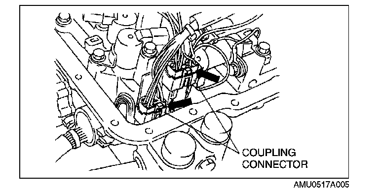
5. Disconnect coupling connector between the solenoid valves and the terminal component.
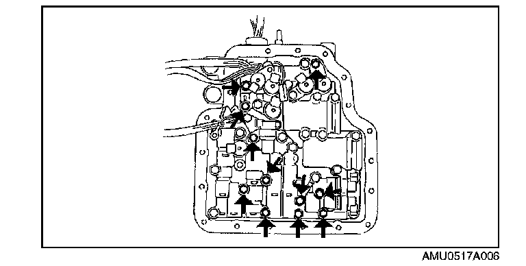
6. Remove the bolts which secure the control valve body to the transaxle case as shown in the figure.
Note: When removing control valve body, be careful not to drop the manual valve.
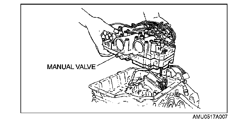
7. Remove the control valve body from the transaxle case.
Caution: If the seal ring has dropped or is scratched, do not reuse it.
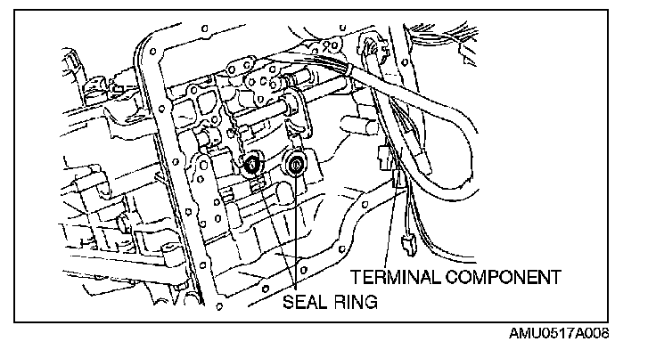
8. Remove the seal rings from the transaxle case.
9. Remove the bracket from coupling connector, then remove the terminal component.
Caution:
^ If the converter housing is hard to remove, lightly tap perimeter of the converter housing using a plastic hammer.
Do not separate the converter housing and the transaxle case using a screwdriver.
Be careful not to scratch mating surfaces of the converter housing and the transaxle case.
^ After removing the converter housing, remove the liquid gasket remaining on the mating surfaces.
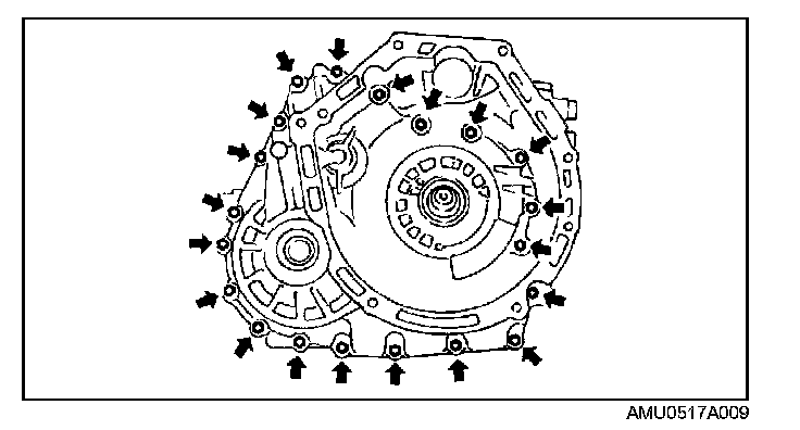
10. Remove the bolts, then remove the converter housing.
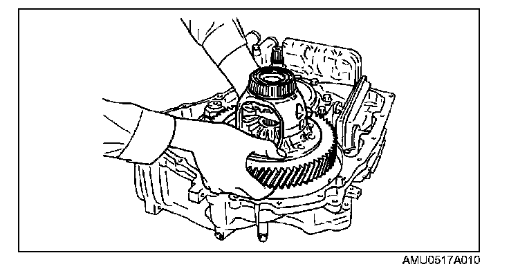
11. Remove the differential component.
12. Remove the oil strainer.
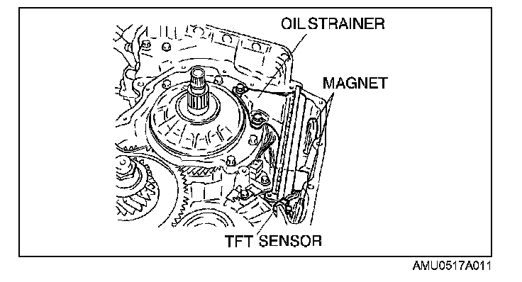
13. Remove the transaxle fluid temperature (TFT) sensor and two magnets.
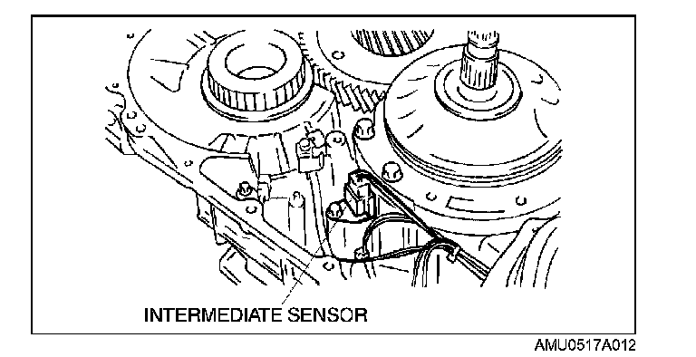
14. Disconnect the intermediate sensor connector.
15. Remove the intermediate sensor with the clip.
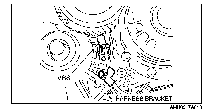
16. Disconnect the vehicle speedometer sensor (VSS) connector.
17. Remove the VSS with the clip and harness bracket.
Note: Do not reuse the O-ring.
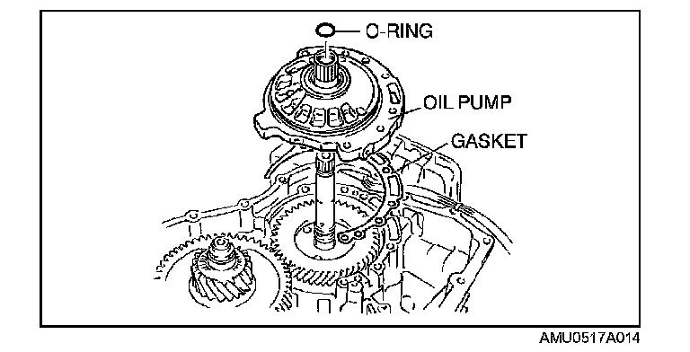
18. Remove the O-ring from the input shaft.
19. Remove the bolts, then remove the oil pump component.
Caution: If the oil pump gasket is bent or scratched, do not reuse it.
20. Remove the oil pump gasket.
Note: Do not reuse the seal rings.
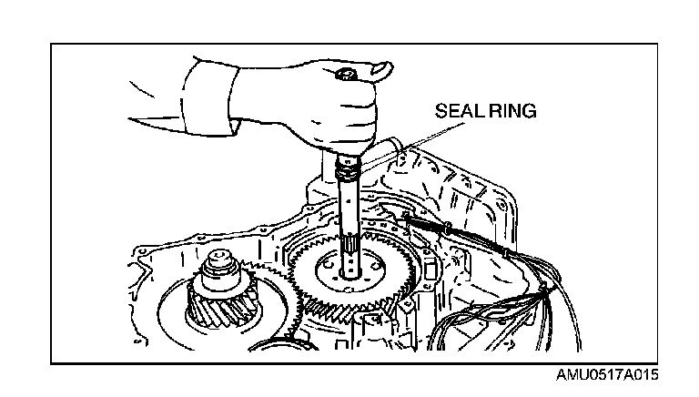
21. Pull out the input shaft.
22. Remove the seal rings from the input shaft.
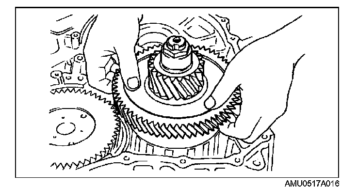
23. Remove the reduction gear component.
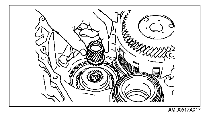
24. Remove the sun gear on the reduction gear.
Note: Do not reuse the anchor end bolt.
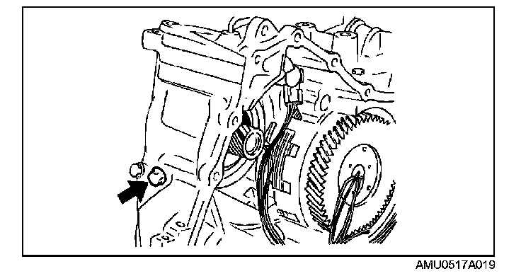
25. Remove the anchor end bolt which secures the reduction brake band.
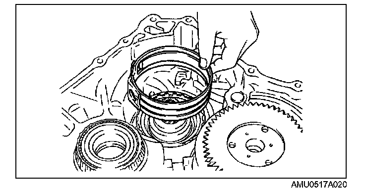
26. Remove the reduction brake band.
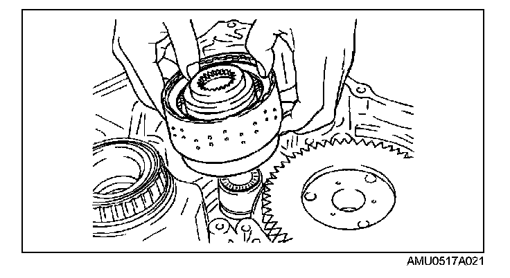
27. Remove the direct clutch component.
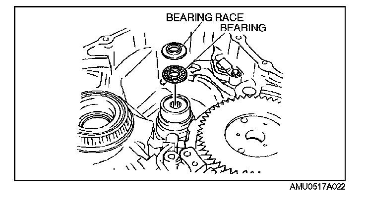
28. Remove the bearing race and bearing from one way clutch inner race.
Caution:
^ If the end cover is hard to remove, lightly tap perimeter of the end cover using a plastic hammer.
Do not separate the end cover and the transaxle case using a screwdriver.
Be careful not to scratch mating surfaces of the end cover and the transaxle case.
^ After removing the end cover, remove the liquid gasket remaining on the mating surfaces.
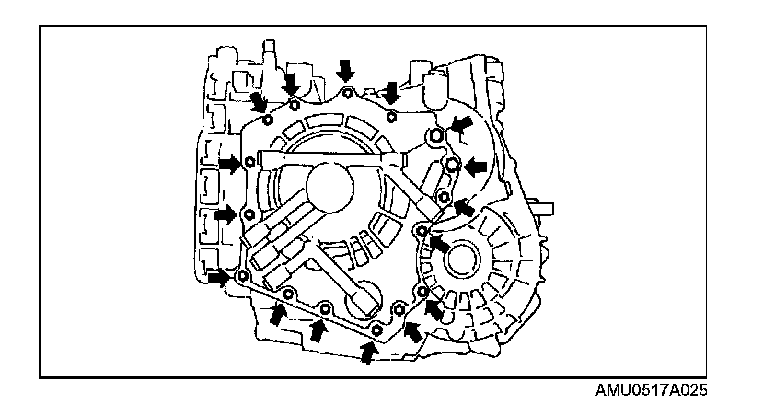
29. Remove the bolts, then remove the end cover.
Note: Do not reuse the O-ring.
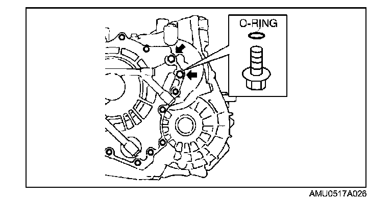
30. Remove the O-rings from two bolts.
Caution: When removing the bolts, be careful not to drop the one-way clutch inner race.
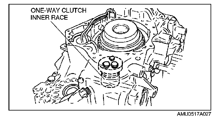
31. Remove the bolts which secure the one-way clutch inner race.
Note: Do not reuse the O-ring.
32. Remove the O-rings from two bolts.
33. Remove the one-way clutch inner race.
Note: Do not reuse the seal rings.
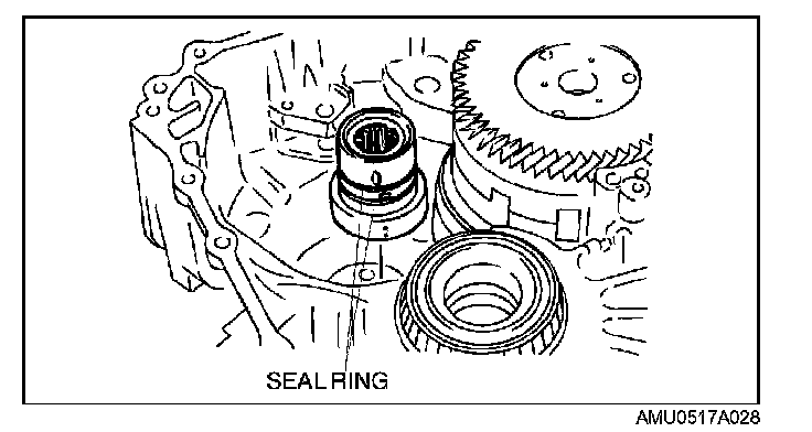
34. Remove the seal rings from the one-way clutch inner race.
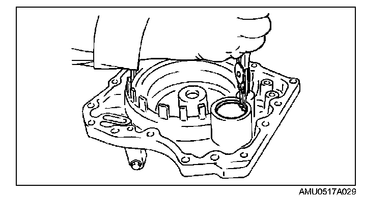
35. Remove the snap ring which secures the 2-4 brake accumulator onto the end cover.
36. Remove the 2-4 brake accumulator cover and spring.
Note: Do not reuse the O-ring.
37. Remove the O-ring from the 2-4 brake accumulator cover.
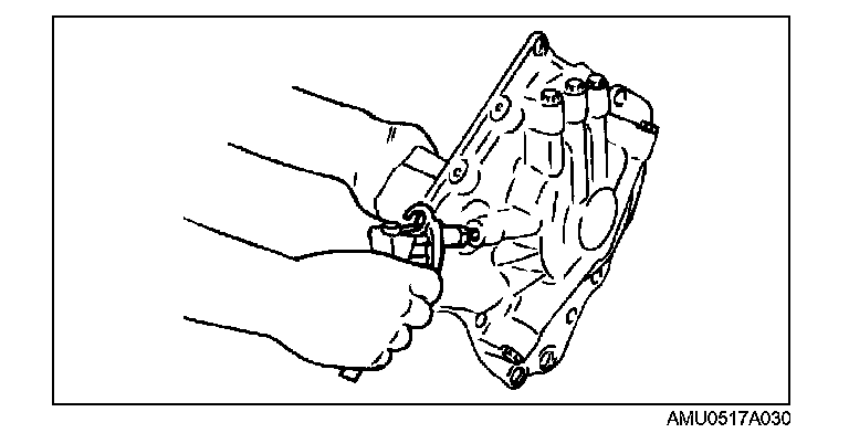
38. Hold the 2-4 brake accumulator piston by hand. Then, blow out the piston using an air gun to blow air into oil circuit as shown in the figure.
Note: Do not reuse the O-ring.
39. Remove the O-rings from the 2-4 brake accumulator piston.
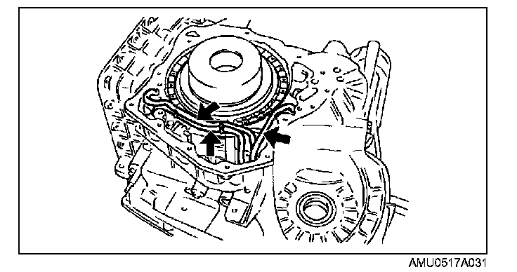
40. Pull out the oil pipes.
41. Disconnect the connector from the turbine sensor.
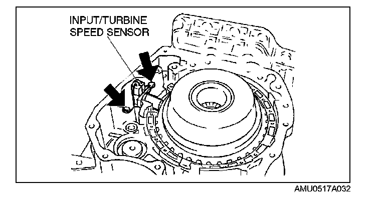
42. Remove the bolts, then remove the turbine sensor.
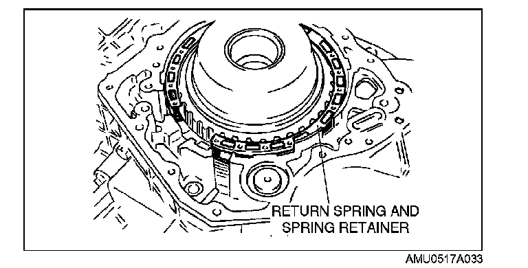
43. Remove the return spring and spring retainer.
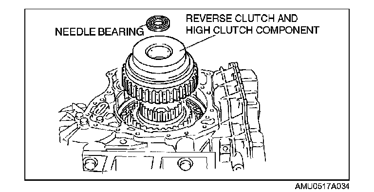
44. Remove the reverse clutch and high clutch component.
45. Remove the needle bearing from the reverse clutch and high clutch component.
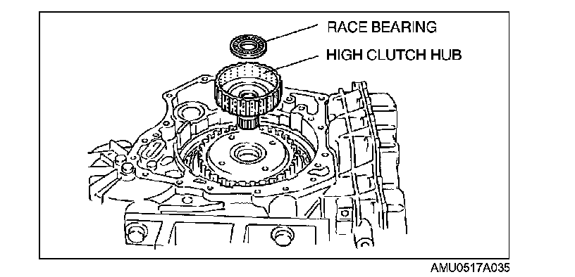
46. Remove the high clutch hub.
47. Remove the race bearing from the high clutch hub.
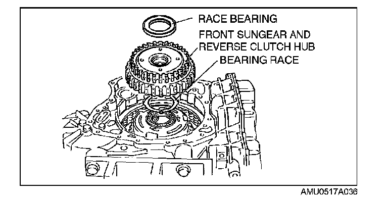
48. Remove the low clutch hub.
49. Remove the race bearing and bearing race from the low clutch hub.
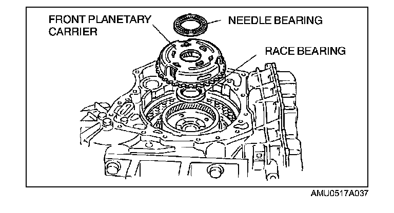
50. Remove the front planetary carrier component.
51. Remove the needle bearing and race bearing from the front planetary carrier component.
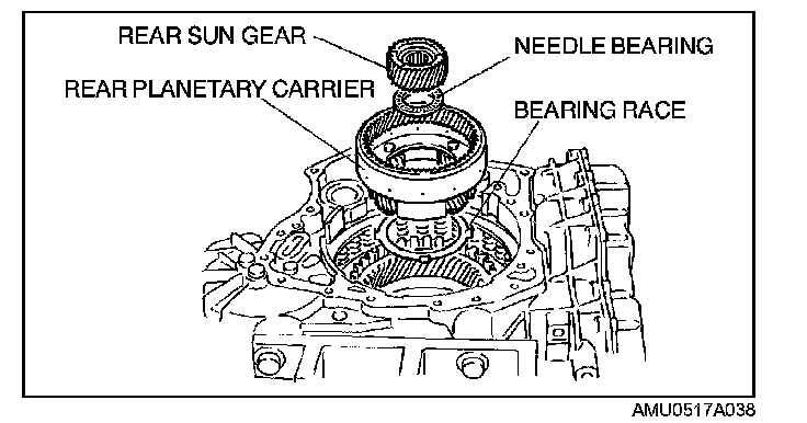
52. Remove the rear sun gear.
53. Remove the rear planetary carrier component.
54. Remove the needle bearing and bearing race from the rear planetary carrier component.
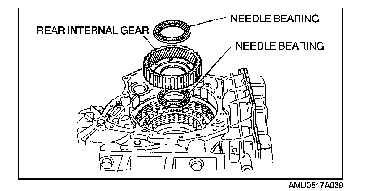
55. Remove the rear internal gear.
56. Remove the needle bearing from the rear internal gear.
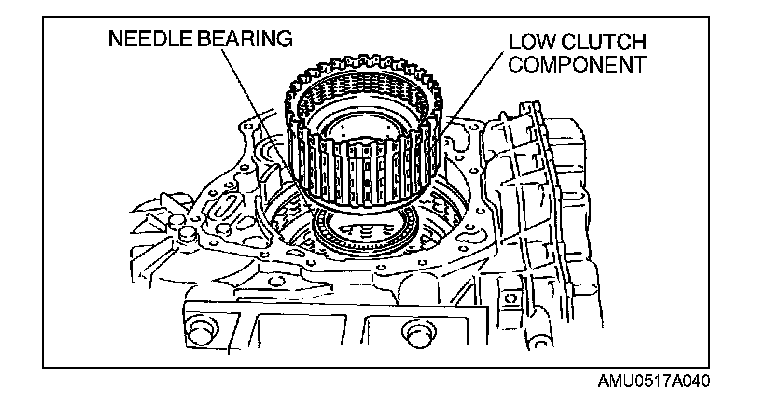
57. Remove the low clutch component.
58. Remove the needle bearing.
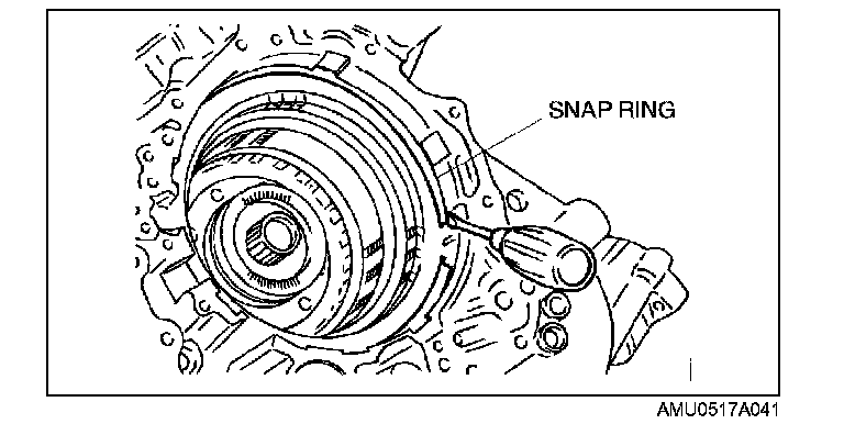
59. Remove the 2-4 brake.
1) Remove the snap ring.
2) Remove 2-4 brake retaining plates, drive plates, and driven plates as a unit.
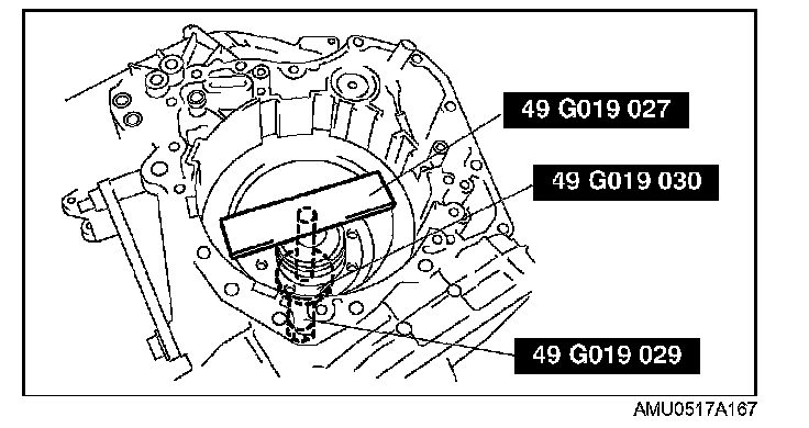
60. Remove the low and reverse brake.
Caution: Depress the spring retainer only enough to remove the snap ring. Overpressing will damage the retainer component edges.
1) Install the SSTs in the transaxle case as shown in the figure.
2) Remove the snap ring.
3) Remove the SSTs.
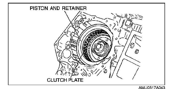
4) Remove the piston and retainer, return spring, and spring retainer.
5) Remove the low and reverse brake dished plate, drive plates, driven plates, and retaining plate as a unit.
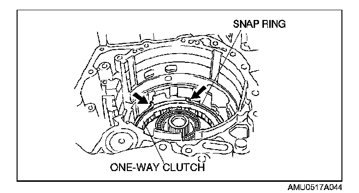
6) Remove the snap ring.
7) Remove the low one-way clutch.
Caution: Be careful not to drop the low one-way clutch rollers.
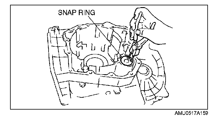
61. Remove the direct clutch accumulator.
1) Remove the snap ring.
Warning: Using compressed air can cause dirt and other particles to fly out, causing injury to the eyes. Wear protective eye wear whenever using compressed air.
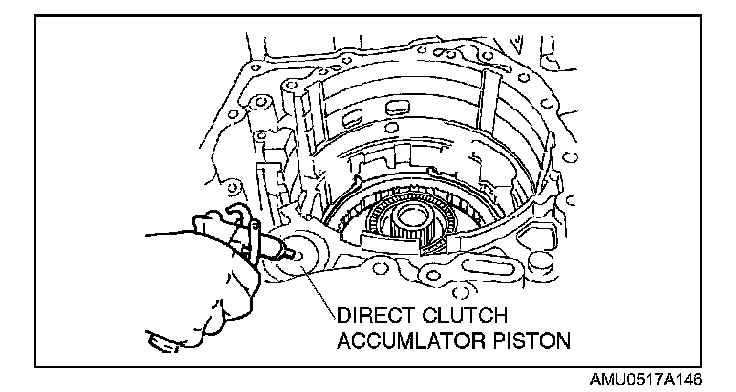
2) Remove the direct clutch accumulator piston by applying compressed air through the hole of the direct clutch accumulator piston.
3) Remove the springs.
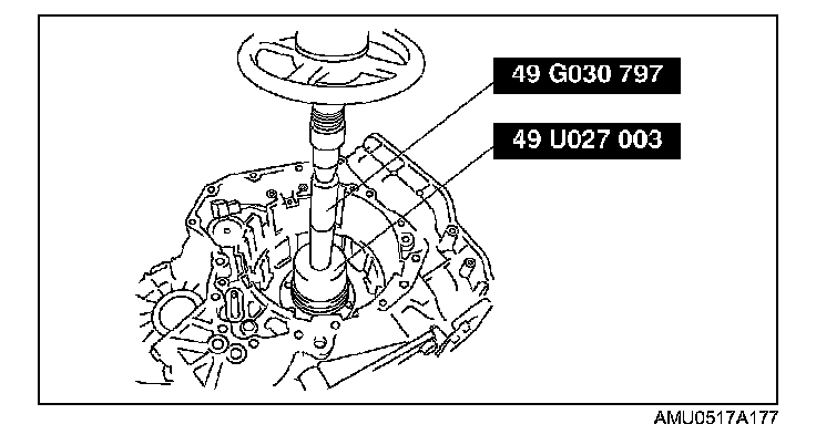
62. Remove the output gear.
1) Remove the installation bolts of output gear.
2) Set the SSTs to the output gear, and remove the output gear using a press.
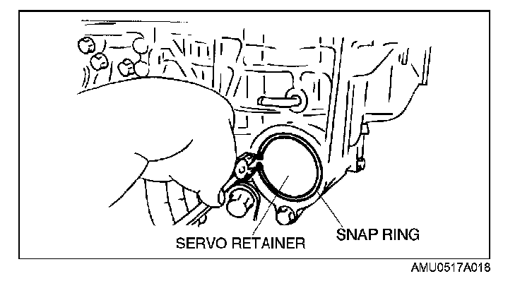
63. Remove the brake band servo.
1) Remove the snap ring.
Warning: Using compressed air can cause dirt and other particles to fly out, causing injury to the eyes. Wear protective eye wear whenever using compressed air.
Caution: Applying compressed air to the assembled clutch pack for longer than 3 seconds at a time will damage the seal.
Do not apply compressed air for more than the aforementioned time when testing the system.
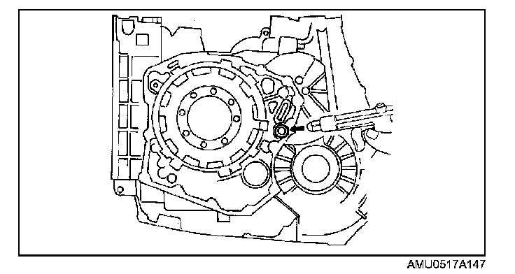
2) Remove the servo retainer and reduction accumulator piston component by applying compressed air as shown.
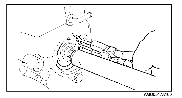
3) Pushing the piston stem using a wood stick, remove the snap ring.
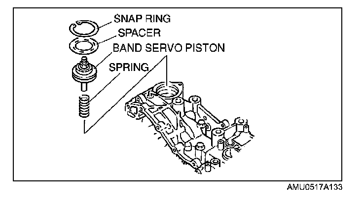
4) Remove the spacer, band servo piston, and spring.
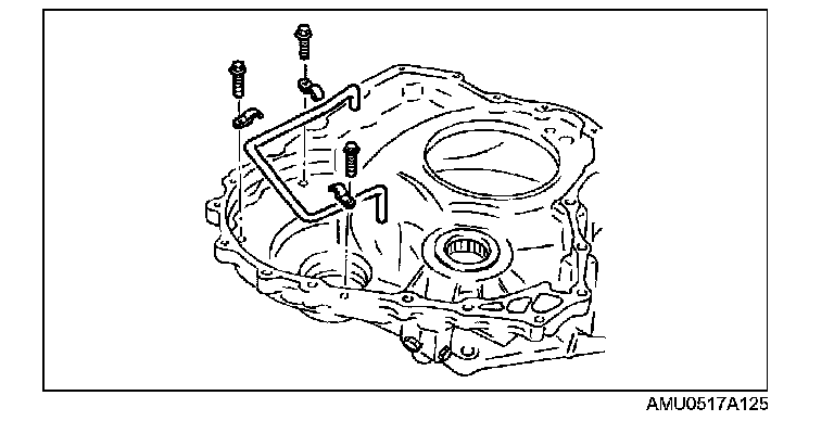
64. Remove the oil pipe from the converter housing.
65. Remove the baffle plate.
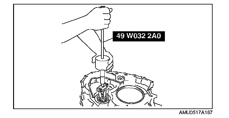
66. Set the SST to the reduction gear bearing outer race, and remove it.