Reading Diagnostic Trouble Codes
Inspection Procedure
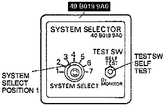
1. Connect the Special Service Tool (SST-49 B019 9A0) System Selector to the data link connector.
2. Set SYSTEM SELECT to position 1.
3. Set the TEST SWITCH to SELF TEST.
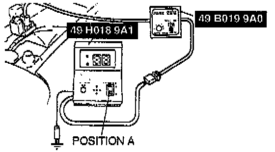
4. Connect the (SST-49 H018 9A1) Self-Diagnosis Checker to the System Selector and a ground.
5. Set the select switch to position A.
6. Turn the ignition switch ON.
7. Verify the "88 flashes on the digital display and the buzzer sounds for 3 Sec. after turning the ignition switch ON.
8. If "88" does not flash, check the main relay, power supply circuit, and data link connector wiring.
9. If "88 flashes and the buzzer sounds continuously for more than 20 Sec., check for a short circuit between the ECM terminal 1 F and the data link connector. Replace the ECM if necessary, perform Steps 3 and 7 again.
10. Note any code numbers and check for the causes by referring to the On-Board Diagnostic Systems-Troubleshooting. Repair as necessary.
11. After repairs, cancel the code numbers by performing the "After-repair procedure".
Principle of Code Cycle
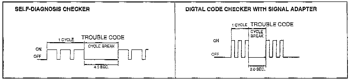
Trouble codes are determined as shown below.
Code Cycle Break
The time between trouble code cycles is 4.0 seconds (the time the buzzer is off).
Second Digit Of Trouble Code (Ones Position)
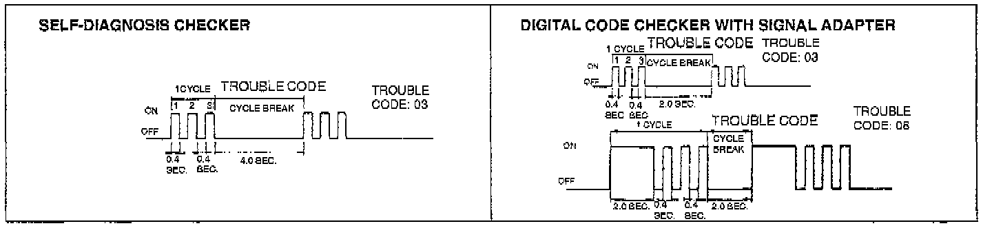
The digit in the ones position of the trouble code represents the number of times the buzzer sounds 0.4 second during one cycle.
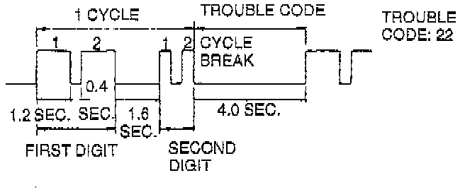
First Digit Of Trouble Code (Tens Position)
The digit in the tens position of the trouble code represents the number of times the buzzer is on 1.2 seconds during one cycle.
The buzzer is off for 1.6 seconds between the long and short pulses.
NOTE: If more than one failure is present, the code numbers will be indicated in numerical order.