Assembly
Precaution1. Replace all O-rings and gaskets with the new ones included in the overhaul kit.
2. Verify that all parts are completely clean before assembly.
3. Assemble parts within 10 minutes after applying sealant. Allow all sealant to cure for at least 30 minutes after assembly before filling the transaxle with transaxle oil.
4. Replace bearing races and bearings as sets.
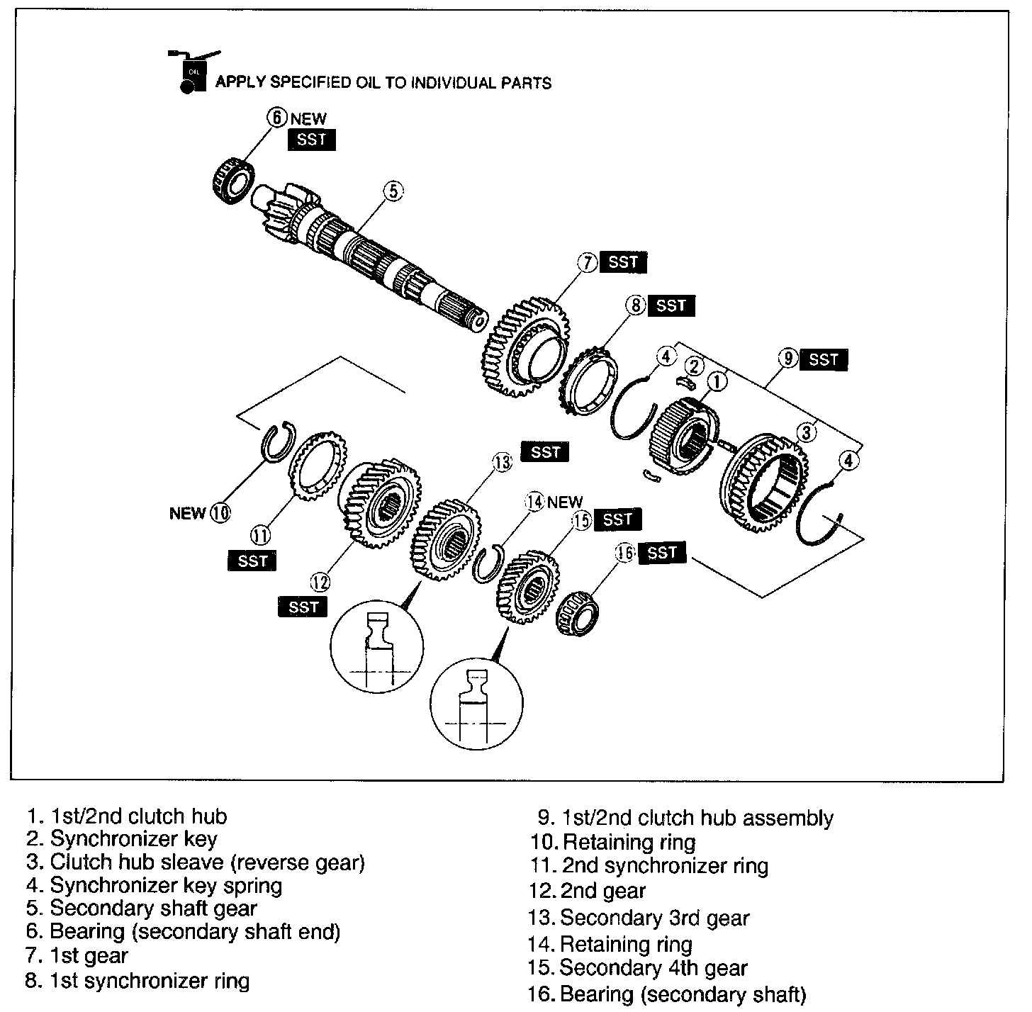
Secondary Shaft Assembly
Assemble in the order shown in the image, referring to Assembly Note.
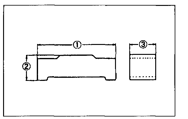
Synchronizer Key Dimensions:
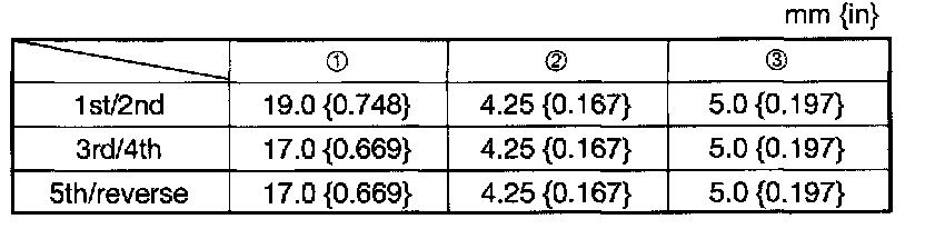
Assembly note
Clutch hub
Synchronizer key dimensions
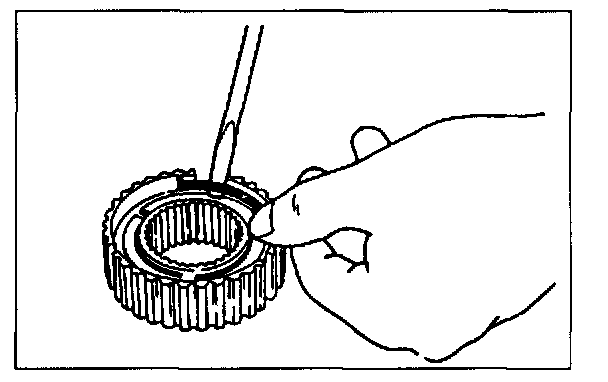
Install the synchronizer keys and springs in the clutch hub.
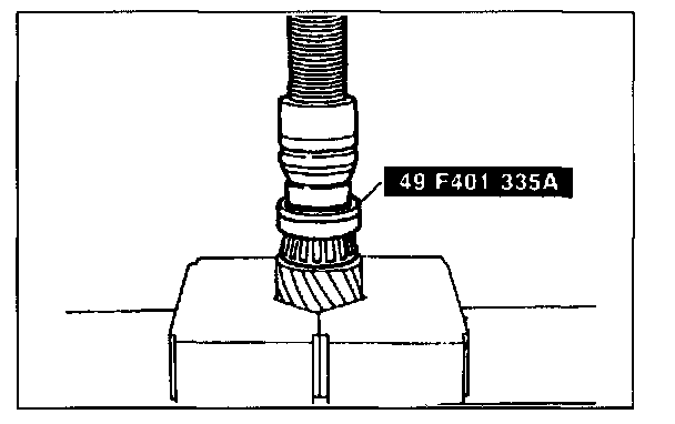
Bearing (secondary shaft end)
Install the new bearing by using the SST.
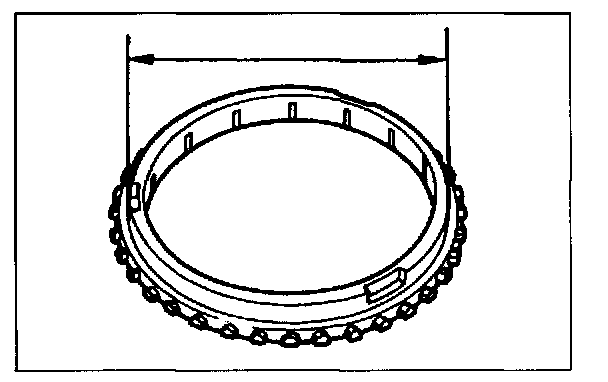
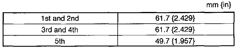
Synchronizer Ring Diameters:
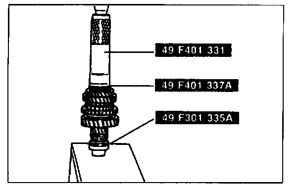
1st gear, 1st synchronizer ring and 1st/2nd clutch hub assembly
Synchronizer ring diameters
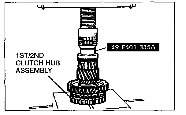
Align the synchronizer ring grooves and synchronizer keys, and install the 1st gear, 1st synchronizer ring and 1st/2nd clutch hub assembly by using the SST.
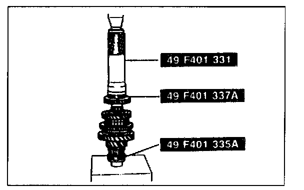
2nd synchronizer ring, 2nd gear, and secondary 3rd gear
1. Install the 2nd synchronizer ring and 2nd gear.
2. Install the secondary 3rd gear by using the SST.
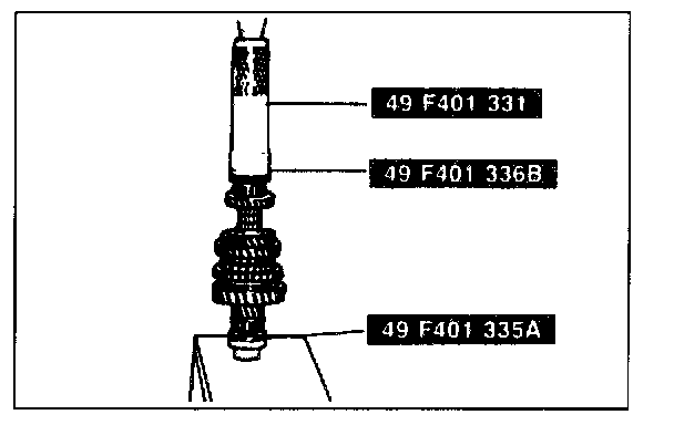
Secondary 4th gear
Install the secondary 4th gear by using the SST.
Bearing (secondary shaft)
1. Install the bearing by using the SST.
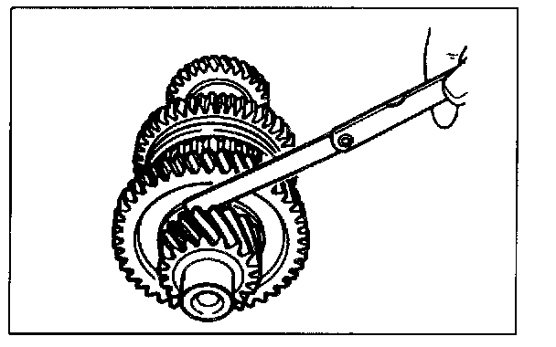
2. Measure the clearance between 1st gear and the differential drive gear.
Clearance: 0.05-0.28 mm (0.002-0.011 in)
Maximum: 0.33 mm (0.013 in)
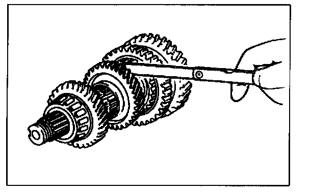
3. Measure the clearance between 2nd gear and the secondary 3rd gear.
Clearance: 0.18-0.51 mm (0.007-0.020 in)
Maximum: 0.56 mm (0.022 in)
4. If not as specified, reassemble the secondary shaft assembly.
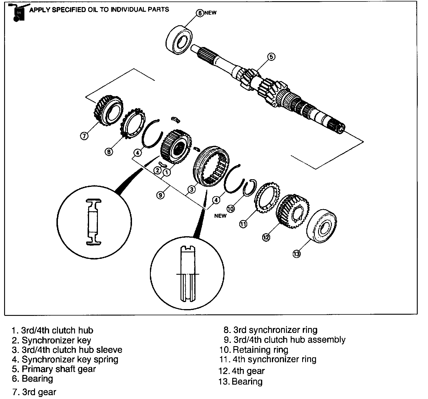
Primary Shaft Assembly
Assemble in the order shown in the image, referring to Assembly Note.
Assembly note
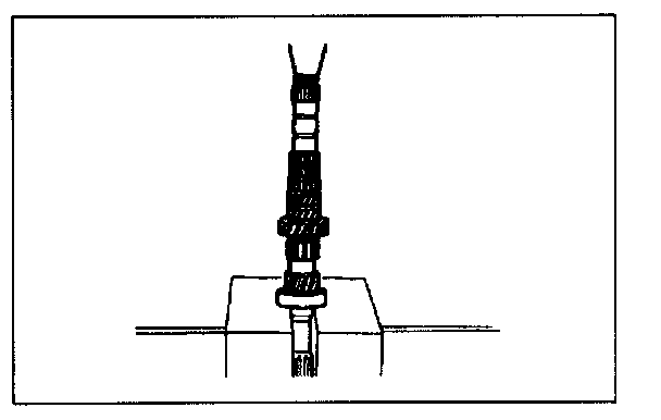
Bearing
Install the new bearing by using a press.
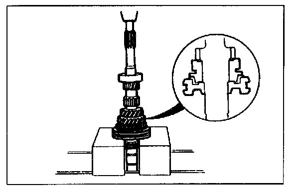
3rd gear, 3rd synchronizer ring, and 3rd/4th clutch hub assembly
Turn the primary shaft over and install the 3rd gear, 3rd synchronizer ring, and 3rd/4th clutch hub assembly by using a press.
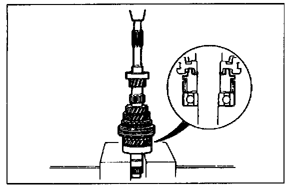
4th synchronizer ring, 4th gear, and bearing
1. Install the retaining ring.
2. Install the 4th synchronizer ring, 4th gear, and bearing by using a press.
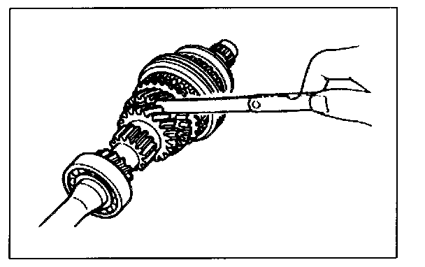
3. Measure the clearance between 3rd gear and 2nd gear.
Clearance: 0.06-0.21 mm (0.002-0.008 in)
Maximum: 0.26 mm (0.010 in)
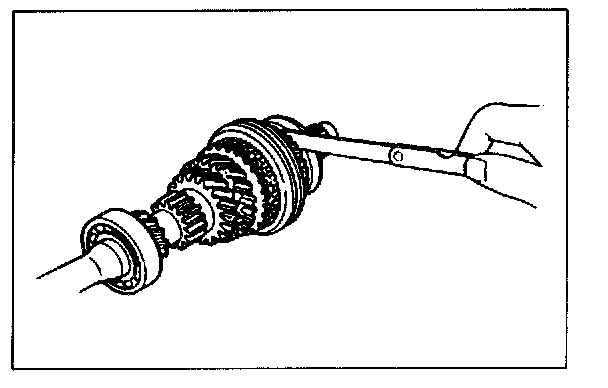
4. Measure the clearance between 4th gear and the ball bearing.
Clearance: 0.14-0.39 mm (0.005-0.015 in)
Maximum: 0.44 mm (0.017 in)
5. If not as specified, reassemble the primary shaft assembly.
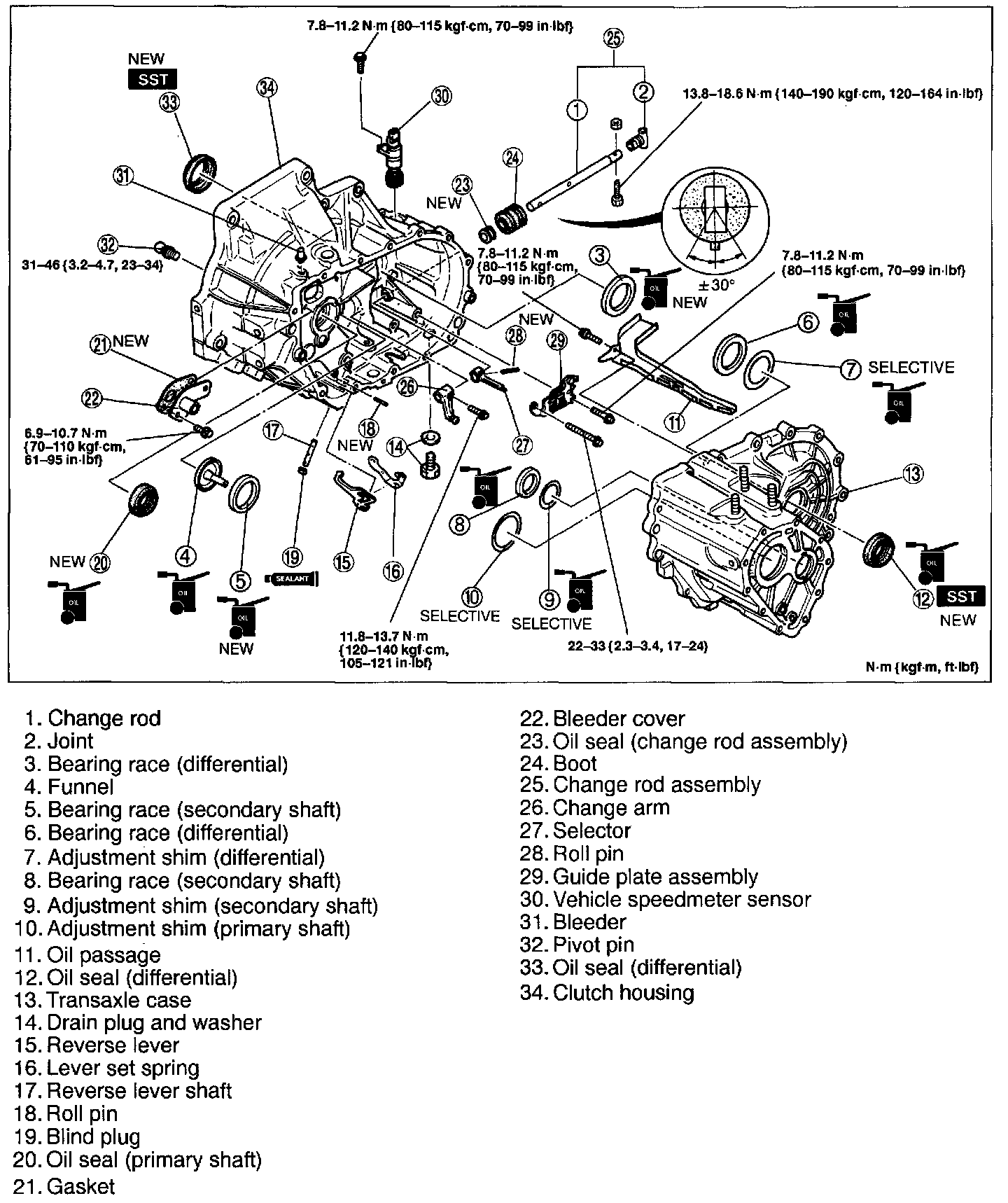
Clutch Housing and Transaxle Case Components
1. Select the adjustment shim(s), referring to Shim Selection.
2. Assemble in the order shown in the image, referring to Assembly Note.

Shim selection
When replacing any of the parts listed in the image, adjust the bearing preload by selecting and installing the proper adjustment shim(s).
Select the shim(s) as follows.
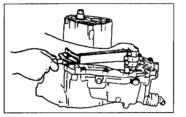
Primary shaft assembly
1. Set the primary shaft assembly into the clutch housing.
2. Install the transaxle case to the clutch housing and tighten the bolts to the specified torque.
Tightening torque: 19-25 N.m (1.9-2.6 kgf.m, 14-18 ft.lbf)
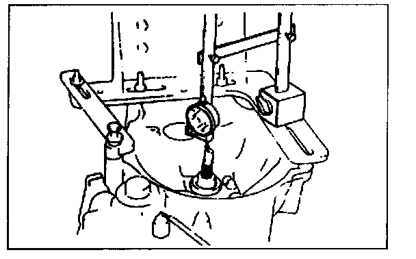
3. Mount a dial indicator to the transaxle hanger and measure the primary shaft clearance.
Clearance: 0.005-0.100 mm (0.0002-0.0039 in)
4. Select the closest shim (on the thin side) from the image.
Adjustment Shim Thickness:

Adjustment shim thickness
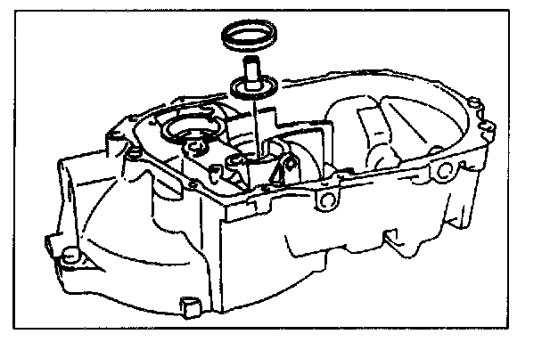
Secondary shaft bearing preload
1. Install the funnel and bearing race into the clutch housing.
2. Set the secondary shaft into the clutch housing.
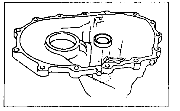
3. Install the secondary shaft bearing race into the transaxle case.
4. Install the transaxle case to the clutch housing and tighten the bolts to the specified torque.
Tightening torque: 19-25 N.m (1.9-2.6 kgf.m, 14-18 ft.lbf)
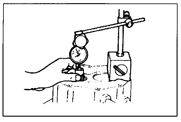
5. Mount a dial indicator to the transaxle case and measure the secondary shaft end play.
6. Select the shim as follows.
a. Add 0.03mm (0.0012 in) to the thrust clearance.
b. Add 0.08mm (0.0031 in) to the thrust clearance.
c. Select the thickest shim in the range from (a) to (b) from the image.
Example: 0.22 mm (0.009 in)
0.22 mm (0.009 in) +0.03 mm (0.001 in) = 0.25 mm (0.010 in)
0.22 mm (0.009 in) +0.08 mm (0.003 in) = 0.30 mm (0.012 in)
Range: 0.25 mm (0.010 in)-0.30 mm (0.012 in) Select the 0.30 mm (0.012 in).
Adjustment Shim Thickness:

Adjustment shim thickness
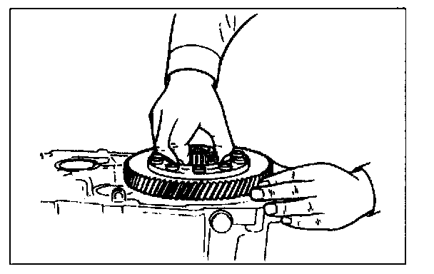
Differential
1. Install the bearing race into the clutch housing.
2. Set the differential assembly into the clutch housing.
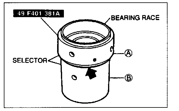
3. Set the transaxle case side bearing race into the SST (selector).
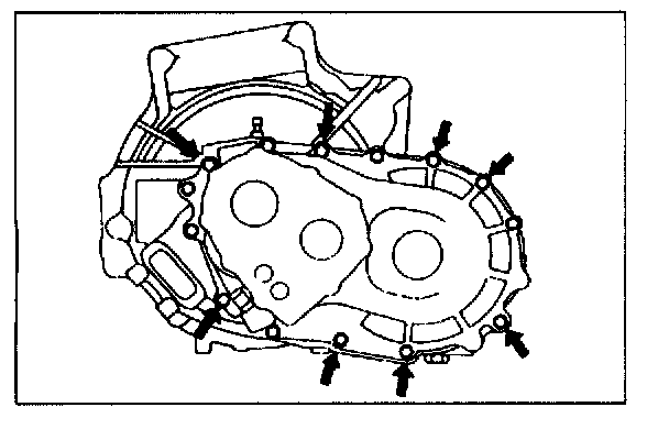
4. Set the SST (collars) in the positions shown in the image.
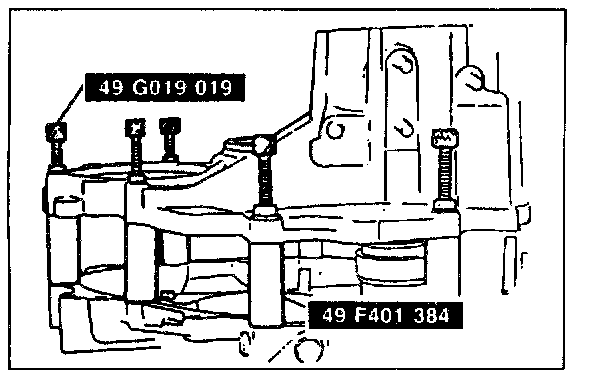
5. Tighten the SST (bolts) to the specified torque.
Tightening torque: 19-25 N.m (1.9-2.6 kgf.m, 14-18 ft.lbf)
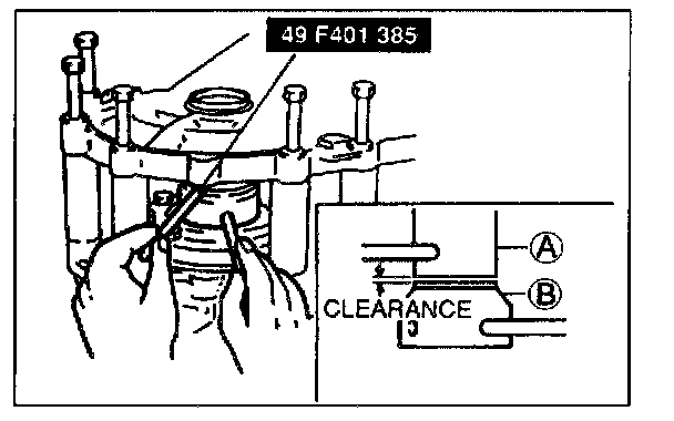
6. To seat the bearings, mount the bars on parts A and B of the selector, and turn the selector so that the gap is widened. Turn until the SST can no longer be moved.
7. Turn in the reverse direction until the gap is eliminated.
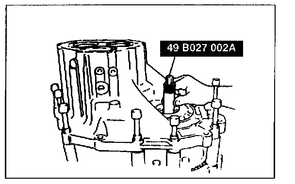
8. Install the SST to the differential pinion shaft through the transaxle case.
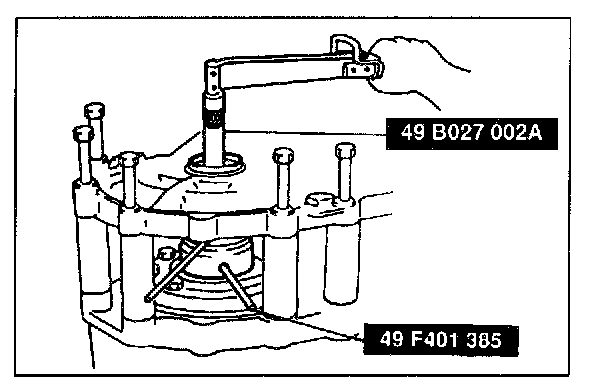
9. Turn the SST with a torque wrench. Adjust the SST (selector) with the SST (bars) until the specified preload is obtained.
Preload: 0.03-0.74 N.m (0.3-7.6 kgf.cm, 0.26-6.60 in.lbf)
10. Remove the SST.
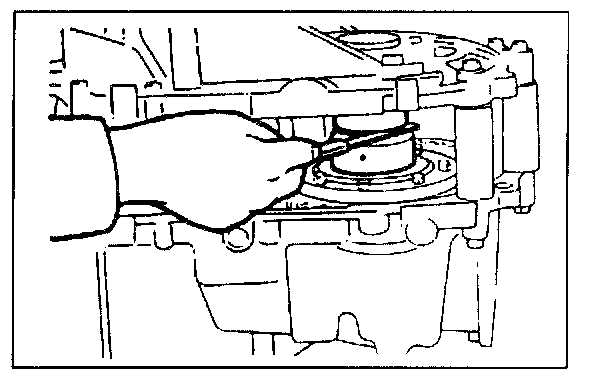
11. Measure the clearance around the entire circumference of the SST (selector).
12. Select the proper adjustment shim(s) to be used for the differential by referring to the image and selecting the shim which is nearest (on the thick side) to the largest measured clearance in the selector.
Adjustment Shim Thickness:

Adjust shim thickness
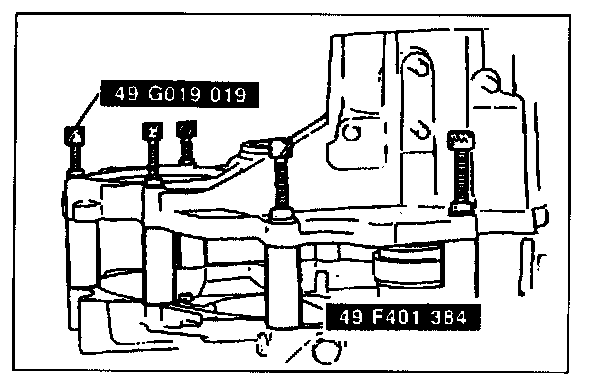
13. Remove the SST (bolts).
14. Remove the transaxle case and the SST (collars).
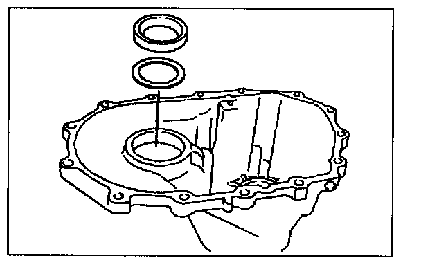
15. Remove the bearing race from the SST (selector).
16. Install the selected shim(s) and the bearing race into the transaxle case.
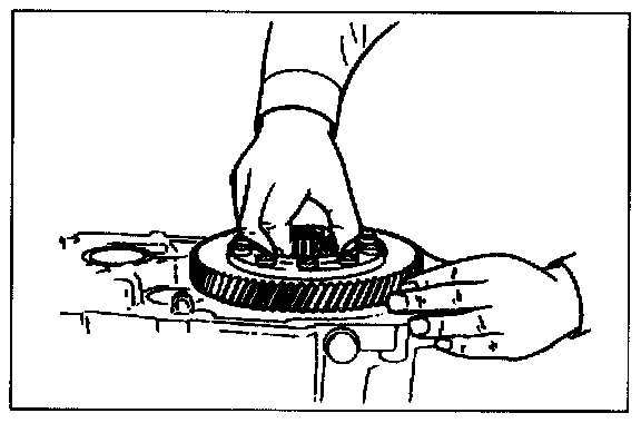
Bearing preload (differential)
Measure the preload as follows.
1. Set the differential assembly into the clutch housing.
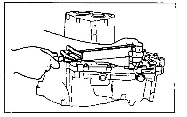
2. Install the transaxle case onto the clutch housing.
Tightening torque: 19-25 N.m (1.9-2.6 kgf.m, 14-18 ft.lbf)
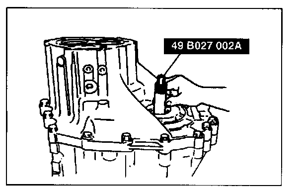
3. Install the SST to the differential pinion shaft through the transaxle case.
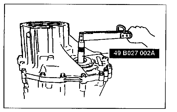
4. Measure the bearing preload.
Preload: 0.03-0.74 N.m (0.3-7.6 kgf.cm, 0.26-6.60 in.lbf)
5. If not as specified, readjust the bearing preload.
6. Remove the SST.
7. Remove the transaxle case and differential assembly.
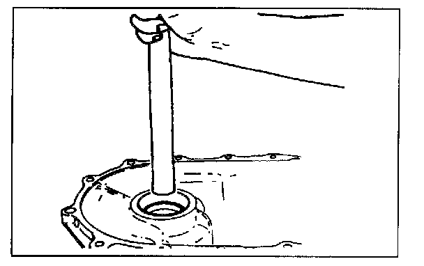
Assembly note
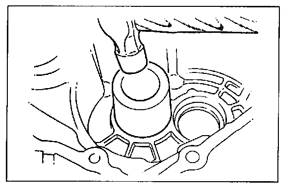
Bearing race (differential)
Install the adjustment shim(s) and install the bearing race by using a suitable pipe.
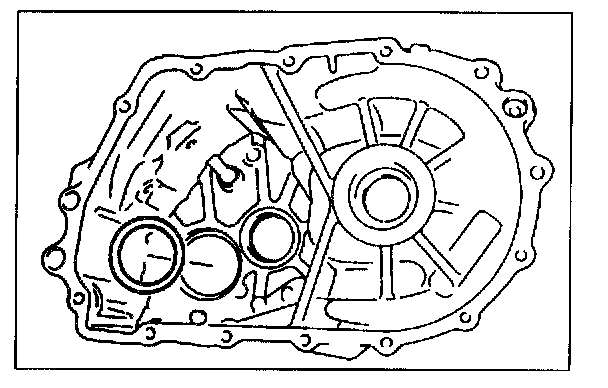
Bearing race (secondary shaft)
1. Apply transaxle oil to the outer edge of the bearing race.
2. Install the selected adjustment shim(s) and the bearing race by using a suitable pipe.
Adjustment shim (primary shaft)
Apply transaxle oil to the selected adjustment shim(s) and install it.
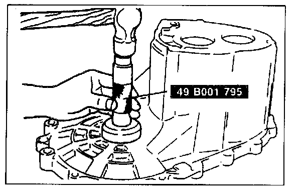
Oil seals (differential)
1. Using the SST and a hammer, tap the new oil seal in evenly until the SST contacts the transaxle case.
2. Coat the lip of the oil seal with transaxle oil.
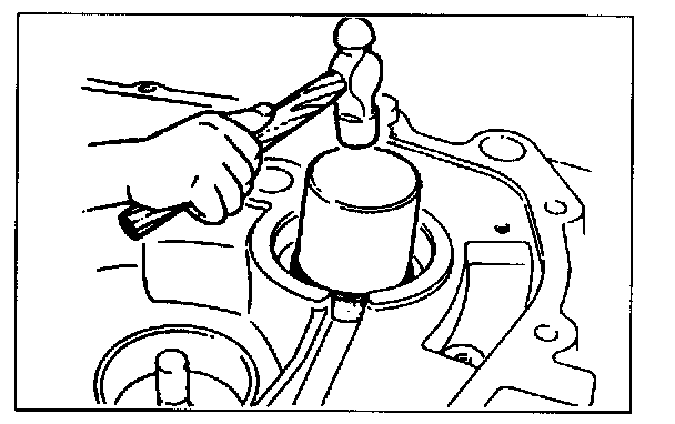
Oil seal (primary shaft)
1. Apply transaxle oil to outer edge of a new oil seal.
2. Install the oil seal by using a suitable pipe.
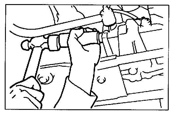
Oil seal (change rod assembly)
1. Install a new oil seal by using a suitable pipe.
2. Coat the lip of the oil seal with transaxle oil.
Outer diameter of pipe: 26 mm (1.02 in)
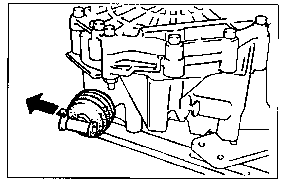
Boot
Install the boot onto the change rod assembly so that the drain hole is facing downward when mounted on the vehicle.
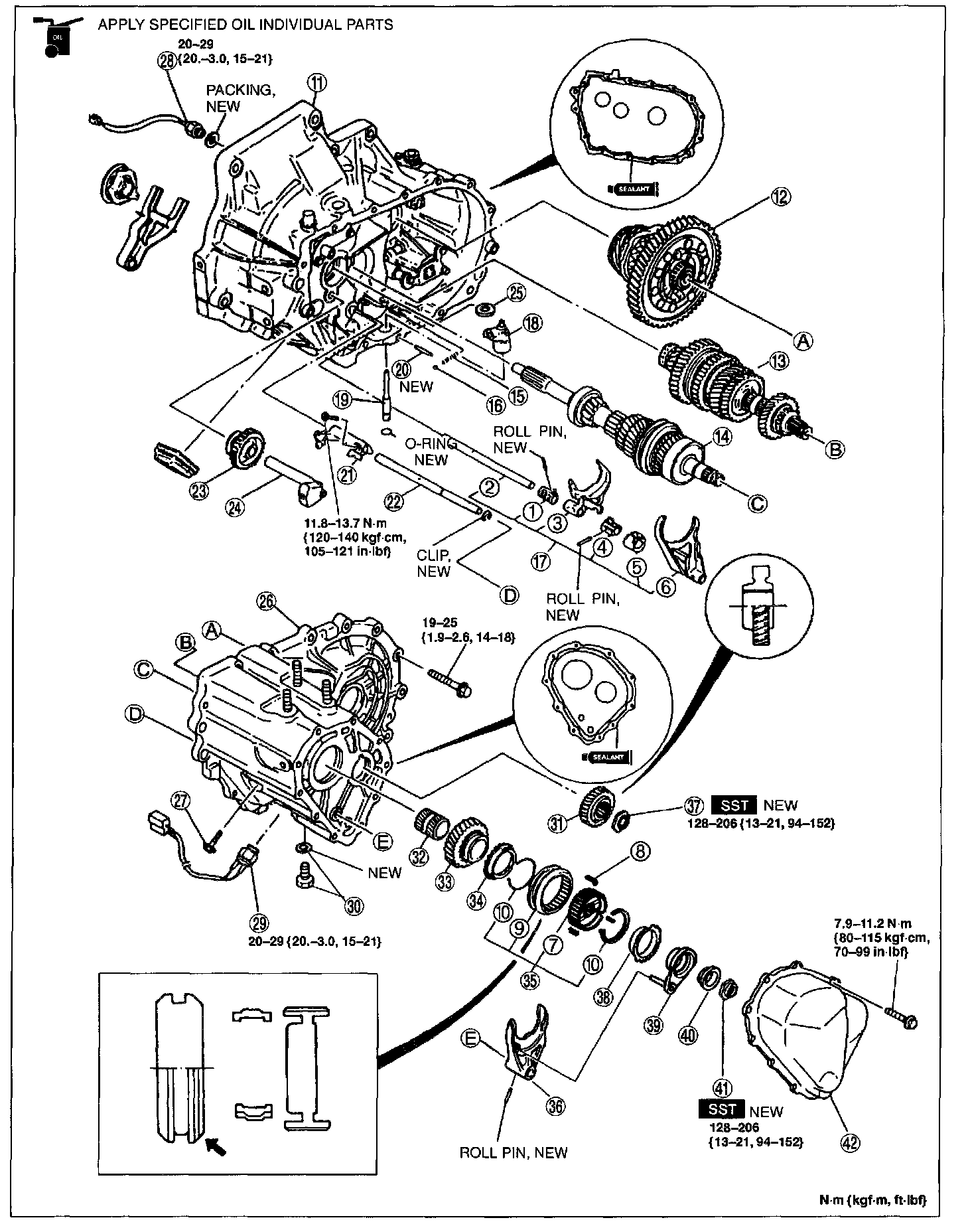
5th / Reverse Gear and Housing Parts
Assembly in the order shown in the image, referring to Assembly Note.
1. Control end
2. Control rod
3. 1st/2nd shift fork
4. Control lever
5. Interlock sleeve
6. 3rd/4th shift fork
7. Clutch hub
8. Synchronizer key
9. Clutch hub sleeve
10. Synchronizer key springs
11. Clutch housing
12. Differential assembly
13. Secondary shaft gear assembly
14. Primary shaft gear assembly
15. Spring
16. Steel ball
17. Shift fork and control rod assembly
18. Crank lever assembly
19. Crank lever shaft
20. Pin
21. 5th/reverse shift rod end
22. 5th/reverse shift rod
23. Reverse idler gear
24. Reverse idler shaft
25. Magnet
26. Transaxle case assembly
27. Lock bolt
28. Neutral switch
29. Back-up light switch
30. Guide bolt and washer
31. Secondary 5th gear
32. Gear sleeve
33. 5th gear
34. 5th synchronizer ring
35. 5th/reverse clutch hub assembly
36. 5th/reverse shift fork
37. Locknut (secondary shaft)
38. Reverse synchronizer ring
39. Primary reverse synchronizer cone assembly
40. Reverse synchronizer gear sleeve
41. Locknut (primary shaft)
42. Rear cover
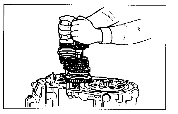
Assembly Note
Primary shaft gear assembly and secondary shaft gear assembly
Install the primary shaft gear assembly and the secondary shaft gear assembly together.
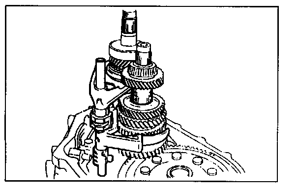
Shift fork and control rod assembly
1. Shift to 2nd gear and position the shift fork and control rod assembly as shown.
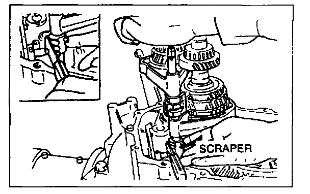
2. Insert the spring seat and spring into the reverse lever shaft. Install the steel ball, and place a scraper against it.
3. With the edge of the control end against the scraper, push the control end in the direction of the arrow so that the ball goes into the shaft. This will line up the rod with the shift rod coupling hole in the clutch housing.
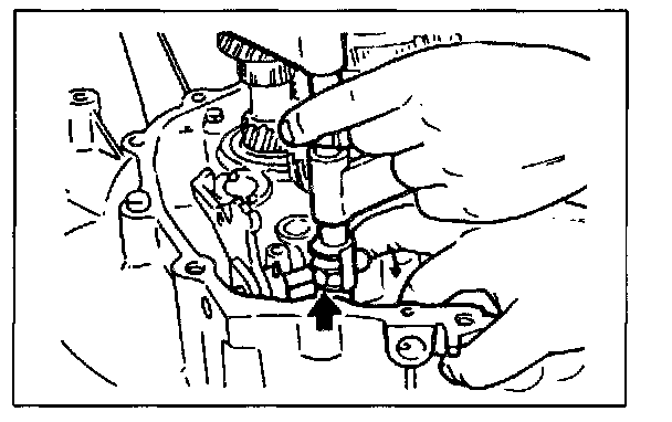
4. Set each clutch hub sleeve to the neutral position, and tap the control rod from above so that the steel ball goes into the center groove (of the three grooves in the control end).
5. Pull the ball part of the control end forward so that the steel ball goes into the detent in the groove.
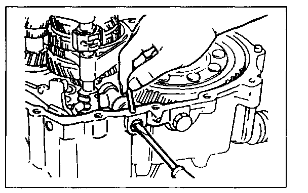
Crank lever assembly and crank lever shaft
1. Install a new O-ring to the crank lever shaft.
2. Fit the crank lever between the change arm and the control end, and connect the crank lever shaft to the crank lever.
3. Align the pin holes of the crank lever shaft and the clutch housing, and insert a new pin.
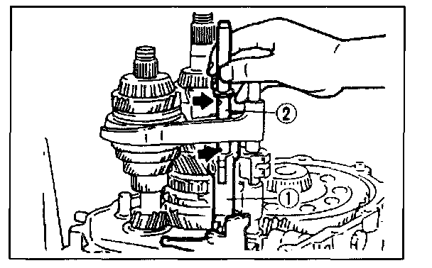
5th / reverse shift rod end and 5th / reverse shift rod
1. Install the shift rod end (1) and the shift rod (2).
2. Align the mark on the shift rod with the mounting bolt hole in the shift rod end as shown in the image, and tighten the gate mounting boll.
Tightening torque: 11.8-13.7 N.m (120-140 kgf.cm, 105-121 ft.lbf)
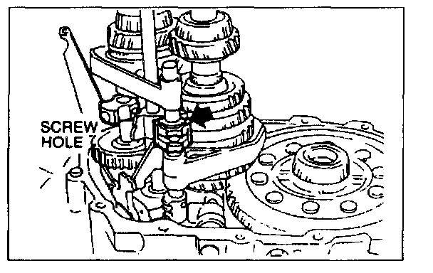
Reverse idler gear and reverse idler shaft
1. Install the reverse idler gear and the reverse idler shaft.
2. Attach the magnet to the clutch housing.
3. Align the end of the interlock sleeve with the control lever (arrow), and face the reverse idler shaft screw hole in the direction shown in the image.
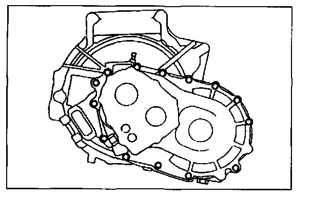
Transaxle case assembly
Apply a thin coat of sealant to the contact surfaces of the clutch housing and transaxle case, and tighten the transaxle case installation bolts to the specified torque.
Tightening torque: 19-25 N.m (1.9-2.6 kgf.m, 14-18 ft.lbf)
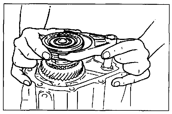
5th/reverse clutch hub assembly and 5th/reverse shift fork
Install the 5th/reverse clutch hub assembly and the 5th/reverse shift fork together.
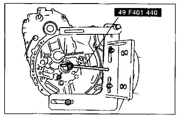
Locknut
1. Shift to 1st gear.
2. Lock the primary shaft by using the SST
3. Tighten new locknuts onto the primary and secondary shafts.
Tightening torque: 128-206 N.m (13-21 kgf.m, 94-152 ft.lbf)
4. Stake the locknuts.
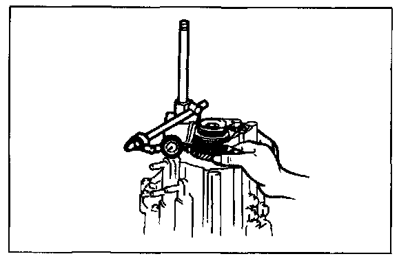
5. Measure the 5th gear thrust clearance by using a dial indicator.
Clearance: 0.08-0.15 mm (0.003-0.006 in)
Maximum: 0.20 mm (0.008 in)
6. If not as specified, reassemble the transaxle.