Disassembly
Precaution1. Clean the transaxle exterior thoroughly with a steam cleaner and/or cleaning solvent before disassembly.
2. Clean the removed parts (except sealed bearings) and all sealing surfaces with cleaning solvent, and dry with compressed air. Clean out all holes and passages with compressed air, and check that there are no obstructions.
3. Wear eye protection when using compressed air to clean components.
5th/Reverse Gear and Housing Parts
1. Measure the thrust clearance between 5th gear and the transaxle case, referring to Preinspection.
2. Disassemble in the order shown in the image, referring to Disassembly Note.
3. Inspect all parts and repair or replace as necessary.
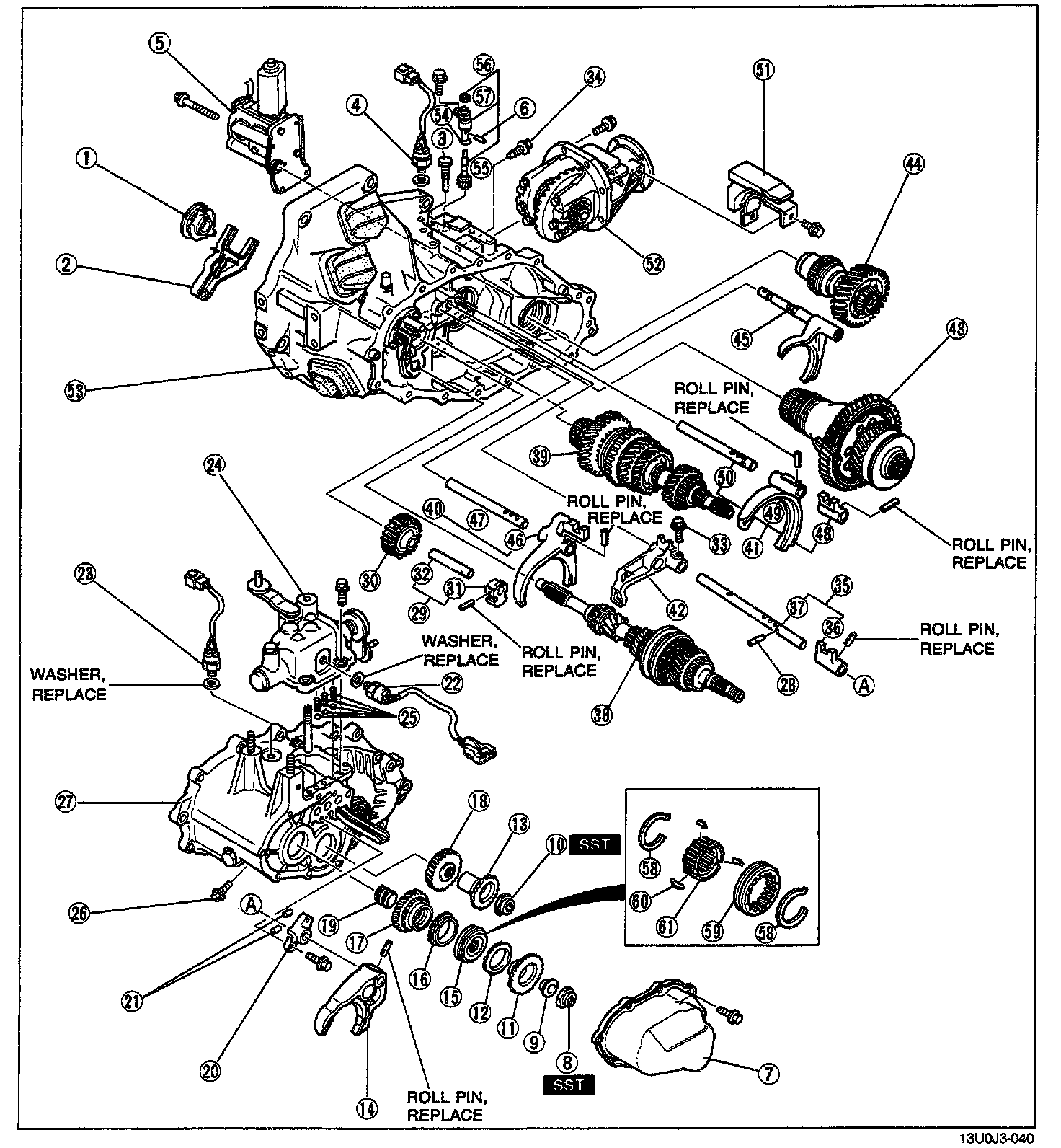
1. Clutch release bearing
2. Clutch release fork
3. Differential lock set bolt
4. Differential lock switch
5. Differential lock motor
6. Speedometer assembly
7. Rear cover
8. Locknut
9. Spacer
10. Locknut
11. Primary reverse synchronizer gear
Inspect gear teeth for damage, wear, and cracks
12. Synchronizer ring
13. Secondary reverse synchronizer gear
Inspect gear teeth for damage, wear, and cracks
14. Shift fork
15. Clutch hub assembly
16. Synchronizer ring
17. Primary 5th gear
18. Secondary 5th gear
Inspect gear teeth for damage, wear, and cracks
19. Gear sleeve
20. Interlock plate
21. Interlock pins
22. Neutral switch
23. Back-up light switch
24. Top cover assembly
25. Steel balls and springs
26. Lock bolt
27. Transaxle case assembly
28. Interlock pin
29. Reverse idler gear shaft assembly
30. Reverse idler gear
31. Reverse idler gear support
32. Reverse idler gear shaft
33. Bolt
34. Steel ball, spring, and bolt
35. Shift rod assembly
36. Shift rod end
37. Shift rod
38. Primary shaft assembly
39. Secondary shaft assembly
40. Shift fork assembly (3rd/4th)
41. Shift fork assembly (1st/2nd)
42. Shift gate
43. Front and center differential assembly
44. Idler gear assembly
45. Center differential lock shift fork
46. Shift fork (3rd/4th)
47. Shift rod (3rd/4th)
48. Shift rod end
49. Shift fork (1st/2nd)
50. Shift rod (1st/2nd)
51. Dynamic damper assembly
52. Transfer carrier assembly
53. Clutch housing assembly
54. O-ring
55. Speedometer driven gear
56. Oil seal
57. Speedometer sleeve
58. Synchronizer key spring
59. Clutch hub sleeve
Inspection page
60. Synchronizer key
61. Clutch hub
Preinspection
5th gear thrust clearance
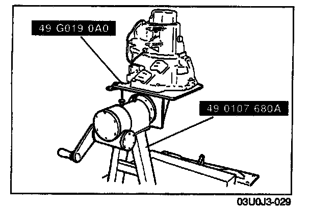
1. Mount the transaxle and transfer carrier on the SST.
2. Remove the rear cover.
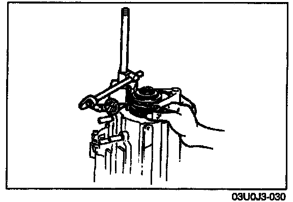
3. Measure the 5th gear thrust clearance with a dial indicator.
Clearance: 0.1 - 0.22 mm (0.0039 - 0.0087 in.)
Maximum: 0.27 mm (0.0106 in.)
4. If the clearance exceeds the maximum, check the contact surfaces of 5th gear and the clutch hub. Replace worn or damaged parts.
Disassembly note
Clutch release bearing, clutch release fork
1. Slide the clutch release fork to the boot.
2. Remove the clutch release bearing.
3. Remove the clutch release fork.
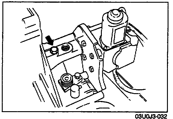
Center differential lock motor
1. Remove the set bolt.
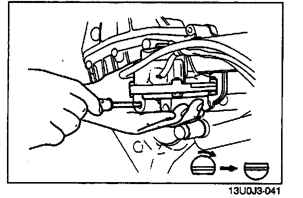
2. Remove the plug and turn the differential lock shift rod 180± clockwise with a screwdriver.
3. Remove the differential lock assembly.
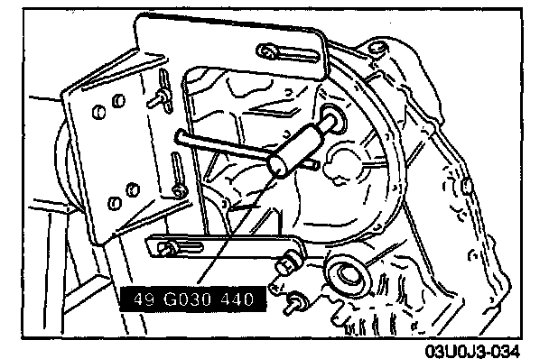
Shift fork, clutch hub assembly
1. Lock the primary shaft with the SST.
2. Shift to 1st or 2nd gear to lock the rotation of the primary shaft.
CAUTION: Do not reuse the removed Locknut.
3. Uncrimp the tabs of the locknuts.
4. Remove the locknuts from the primary and secondary shafts.
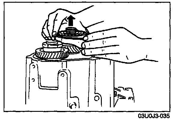
5. Remove the shift fork together with the clutch hub assembly.
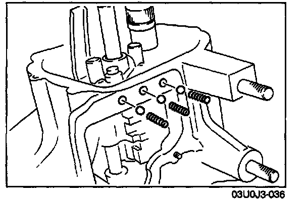
Top cover assembly
1. Remove the top cover assembly.
2. Remove the springs.
3. Remove the steel balls with a magnet.
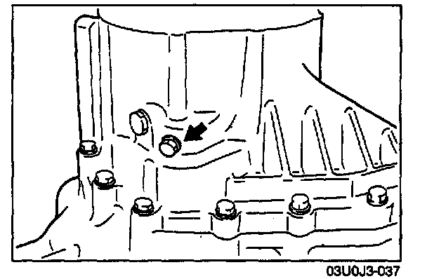
Transaxle case assembly
1. Remove the bolt.
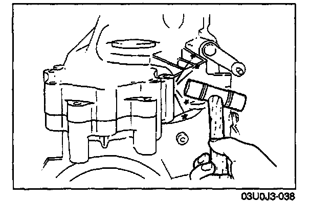
2. Remove the bolts and transaxle case by tapping lightly with a plastic hammer.
3. Remove the magnet.
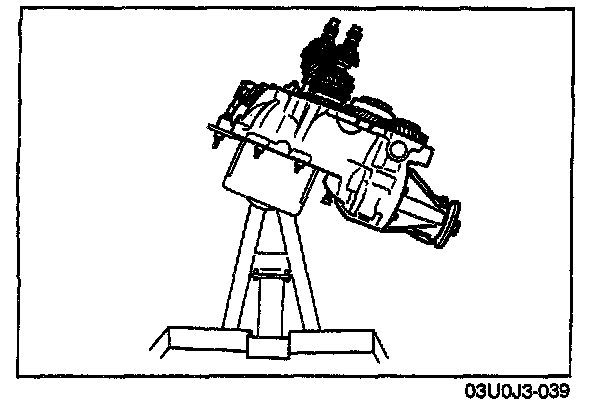
Primary shaft assembly, secondary shaft assembly, front and center differential assembly
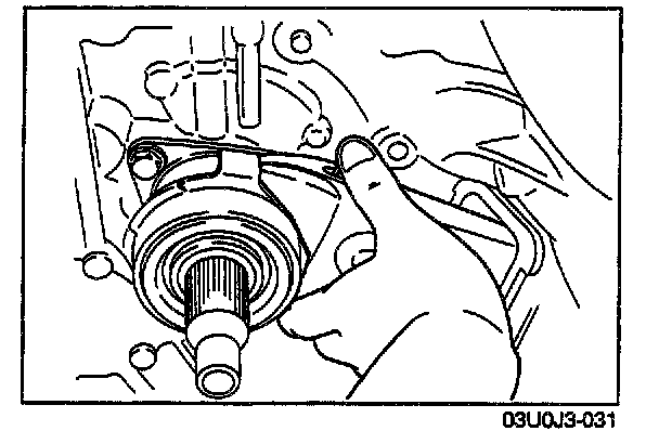
1. Lean the clutch housing as shown.
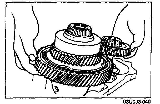
2. Hold the front differential assembly and the idler gear assembly so that primary shaft and secondary shaft can be removed.
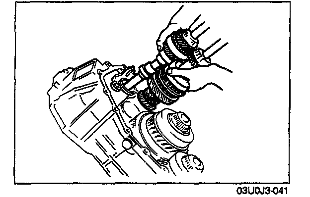
3. Remove the primary shaft assembly, secondary shaft assembly and shift fork assembly together.
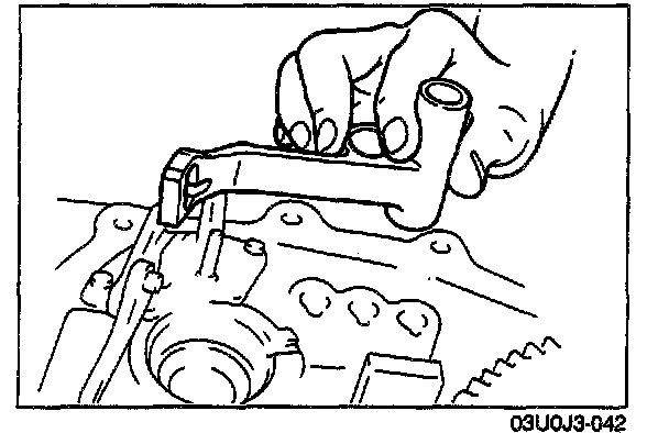
4. Remove the shift gate.
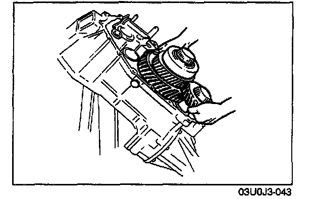
5. Remove the front and center differential assembly, idler gear assembly and center differential lock shift fork assembly together.
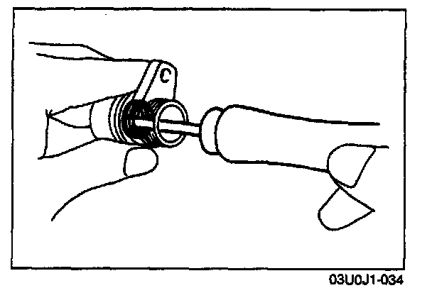
Oil seal (Speedometer gear case)
1. Remove the oil seal as shown in the image.
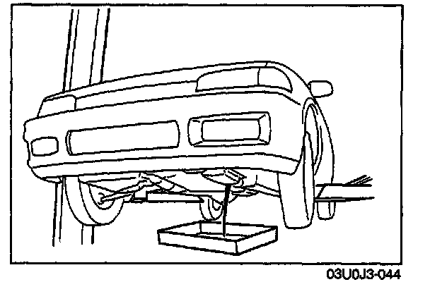
Oil seal (Driveshaft)
Replacement (On-vehicle)
1. Jack up the vehicle and support it with safety stands.
2. Drain the transaxle oil.
3. Remove the concerned front wheel.
4. Remove the splash shield.
5. Separate the front stabilizer from the lower arm.
CAUTION: Do not damage the dust boots.
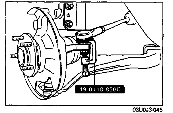
6. Remove the clinch bolt and pull the lower arm downward. Separate the knuckle from the lower arm ball joint.
7. Loosen the nut and disconnect the tie-rod end with the SST.
CAUTION: Do not subject the tripod joint to shock when removing the driveshaft.
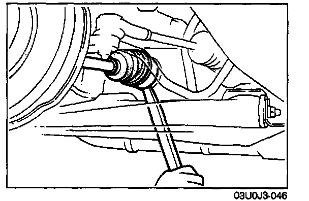
8. Disconnect the driveshaft from the transaxle by prying with a bar inserted between the outer ring and the transaxle.
9. Suspend the driveshaft with a rope.
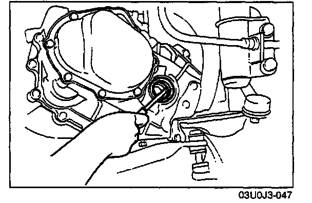
10. Remove the oil seal with a screwdriver.
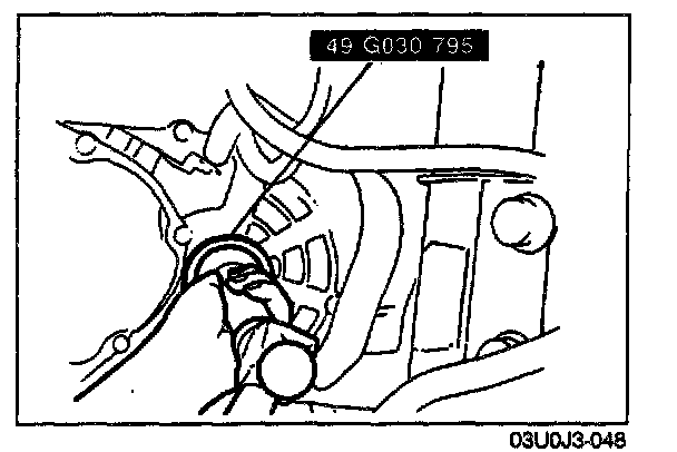
11. Tap the new oil seal into the transaxle case with the SST.
NOTE:
- Tap in until the oil seal installer contacts the case.
- Coat the oil seal lip with transaxle oil.
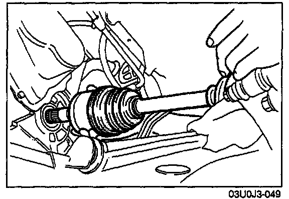
12. Replace the driveshaft end clip with a new one. Insert the driveshaft with the end-gap of the clip facing upward.
13. Install the joint shaft.
Tightening torque: 42 - 62 N-m (4.3 - 6.3 m-kg, 31 - 46 ft-lb)
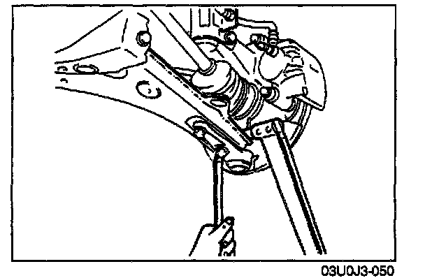
14. Install the lower arm ball joint to the knuckle and tighten.
Tightening torque: 43 - 54 N-m (4.4 - 5.5 m-kg, 32 - 40 ft-lb)
15. Install the tie-rod end to the knuckle and tighten it.
Tightening torque: 29 - 44 N-m (3.0 - 4.5 m-kg, 22 - 33 ft-lb)
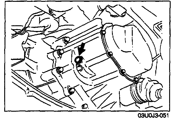
16. Install a new gasket, and the drain plug, and add the specified oil from check plug port.
Tightening torque: 39 - 59 N-m (4.0 - 6.0 m-kg, 29 - 43 ft-lb)
Clutch Housing and Transaxle Case Components
CAUTION: Do not remove an oil seal if not necessary.
1. Disassemble in the order shown in the image, referring to Disassembly Note.
2. Inspect all parts and repair or replace as necessary.
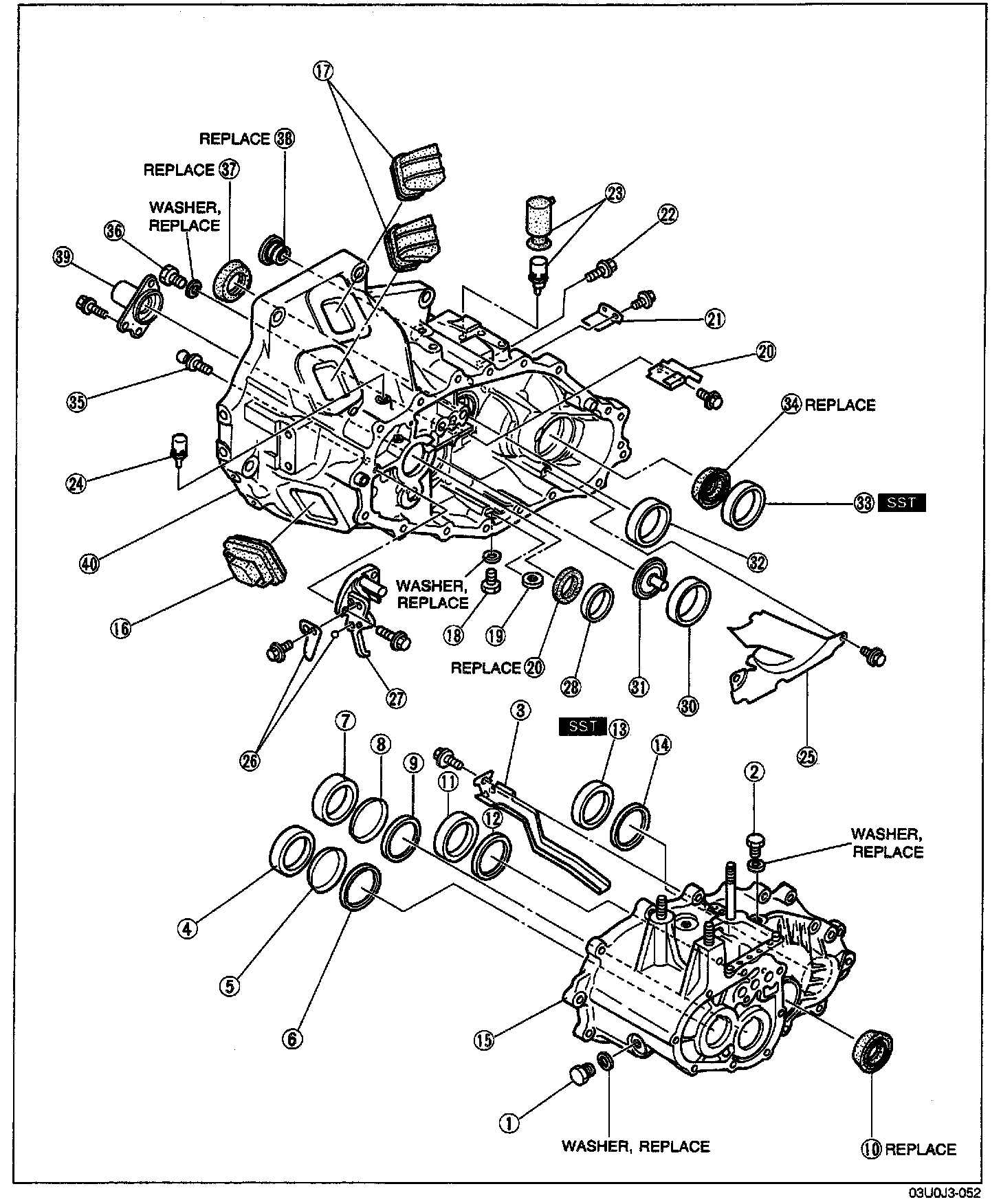
1. Plug
2. Plug
3. Oil guide
4. Bearing outer race
5. Diaphragm spring
6. Adjustment shim
7. Bearing outer race
8. Diaphragm spring
9. Adjustment shim
10. Oil seal
11. Bearing outer race
12. Adjustment shim
13. Bearing outer race
14. Adjustment shim
15. Transaxle case
16. Dust cover
17. Ventilator covers
18. Plug
19. Magnet
20. Oil seal
21. Baffle
22. Bolt
23. Air breather dust boot and air breather
24. Air breather
25. Baffle
26. Lever set spring and steel ball
27. Reverse lever support
28. Bearing outer race
29. Oil seal
30. Bearing outer race
31. Funnel
32. Bearing outer race
33. Bearing outer race
34. Oil seal
35. Pivot pin
36. Plug
37. Oil seat
38. Oil seal
39. Front cover
40. Clutch housing
Disassembly note
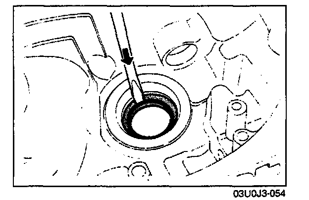
Oil seal
1. Remove the oil seal with a screwdriver.
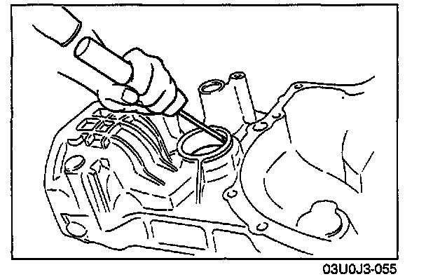
Bearing outer race (Front and center differential side)
1. Remove the bearing outer race with a screwdriver.
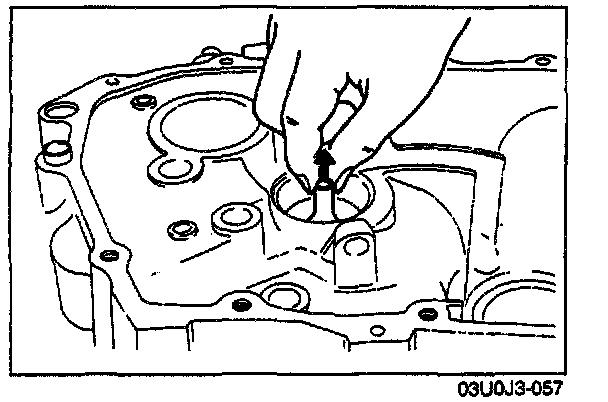
Funnel, bearing outer race
NOTE: Remove the bearing outer race with a screwdriver if necessary.
1. Insert a screwdriver between the clutch housing and bearing outer race.
2. Pry the bearing outer race free.
1. Remove the bearing outer race by lifting out the funnel and race together.
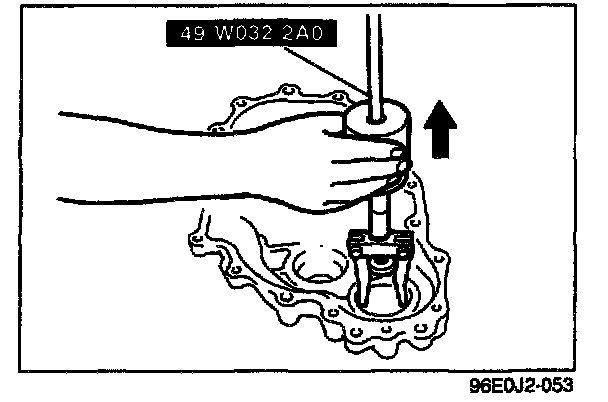
Bearing outer race (Idler gear)
CAUTION: Do not damage the clutch housing and transaxle case.
1. Remove the bearing outer race with the SST.
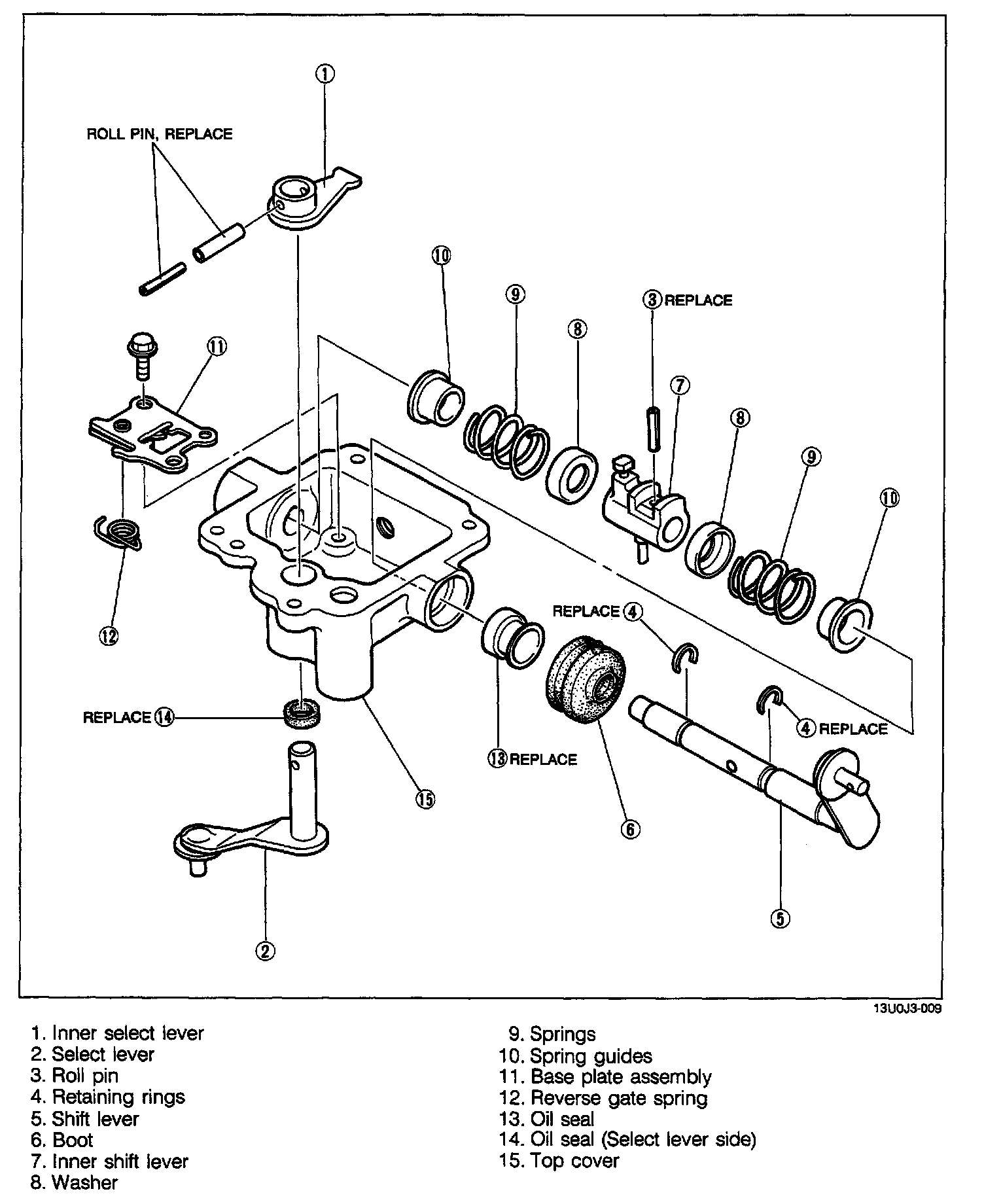
Top Cover Assembly
1. Disassemble in the order shown in the image, referring to Disassembly Note.
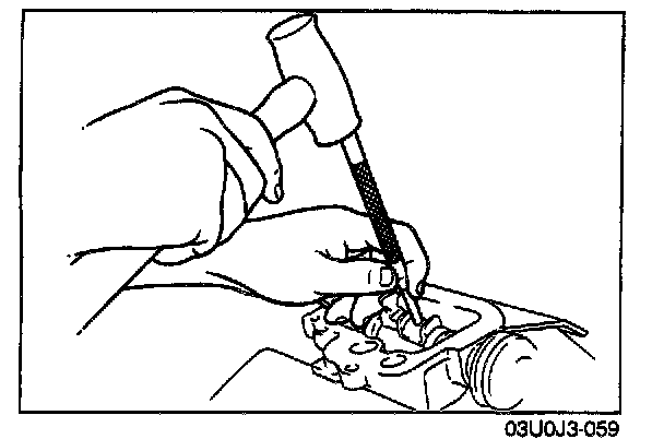
Disassembly note
Roil pin
1. Slide the inner shift cover to the boot side.
2. Remove the roll pin.
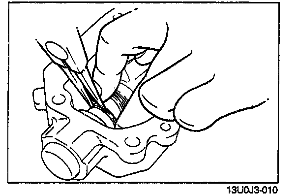
Retaining rings
1. Slide the spring guides away and remove the retaining ring.
2. Remove the inner shift lever.
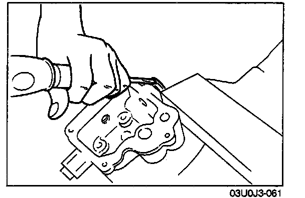
Oil seal
1. Remove the oil seal with a screwdriver.
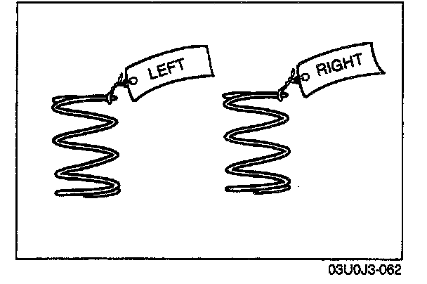
Springs
CAUTION: Do not confuse the springs. The boot side spring is shortest.
NOTE: Mark the springs as shown.
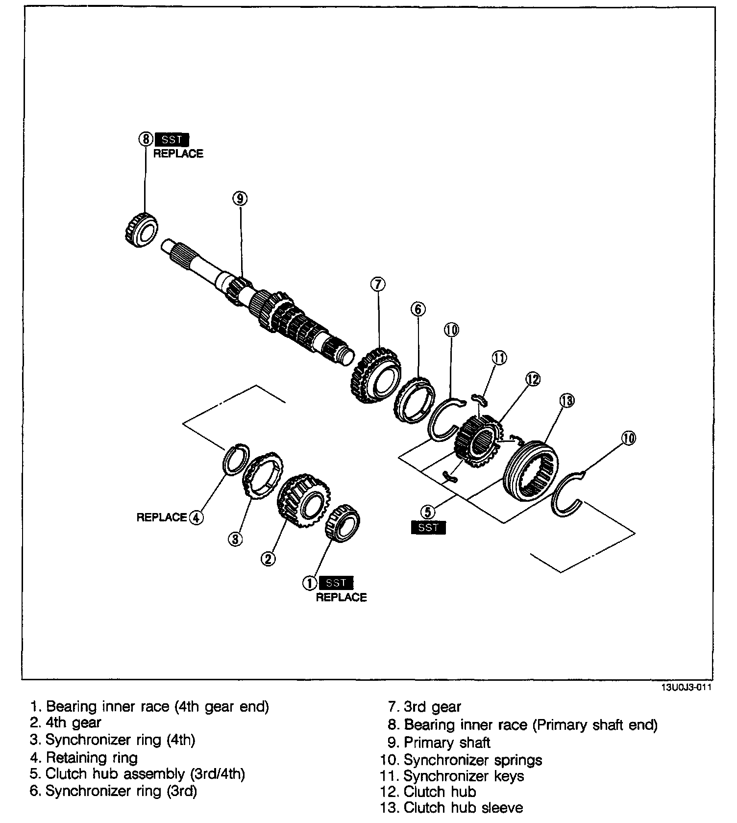
Primary Shaft Assembly
1. Measure the thrust clearance of all gears before disassembly, referring to Preinspection.
2. Disassemble in the order shown in the image, referring to Disassembly Note.
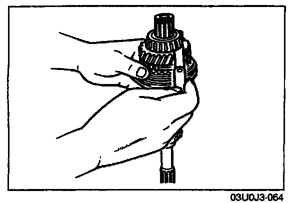
Preinspection
1. Measure the clearance between the 4th gear and bearing inner race.
Clearance: 0.165 - 0.365 mm (0.0064 - 0.0144 in.)
Maximum: 0.415 mm (0.0163 in.)
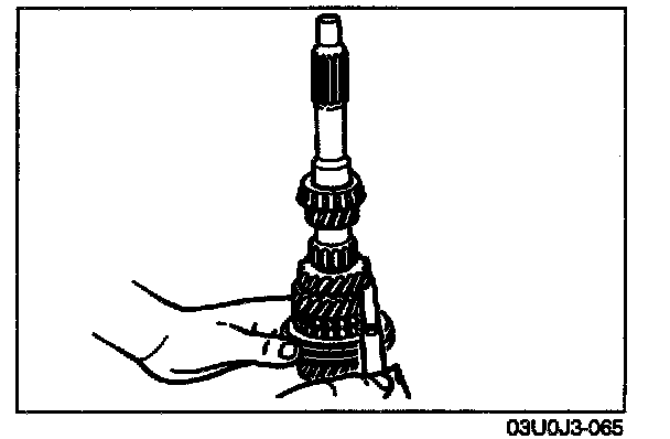
2. Measure the clearance between the 3rd gear and 2nd gear.
Clearance: 0.05 - 0.20 mm (0.002 - 0.008 in.)
Maximum: 0.25 mm (0.010 in.)
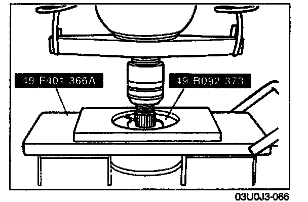
Disassembly note
Bearing inner race (4th gear end)
CAUTION: Hold the shaft with one hand so that ft does not fail.
1. Remove the bearing inner race with the SST.
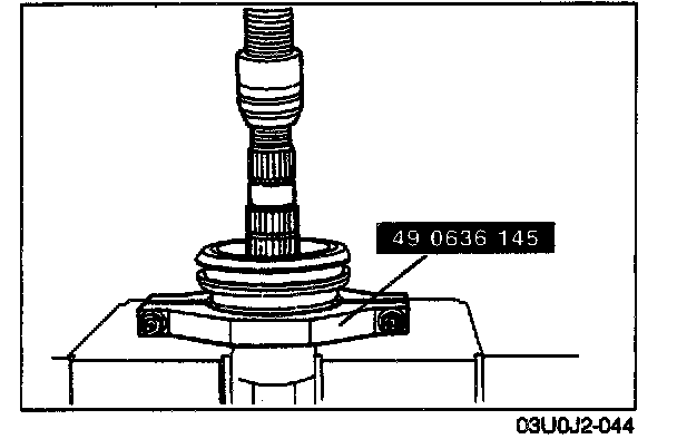
Clutch hub assembly (3rd/4th), synchronizer ring (3rd) and 3rd gear
1. Remove the retaining ring.
CAUTION: Hold the shaft with one hand so that it does not fall.
2. Remove the clutch hub assembly (3rd/4th) synchronizer ring (3rd) and 3rd gear with the SST.
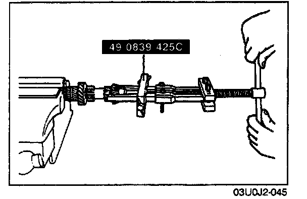
Bearing inner race (Primary shaft end)
1. Remove the bearing inner race with the SST.
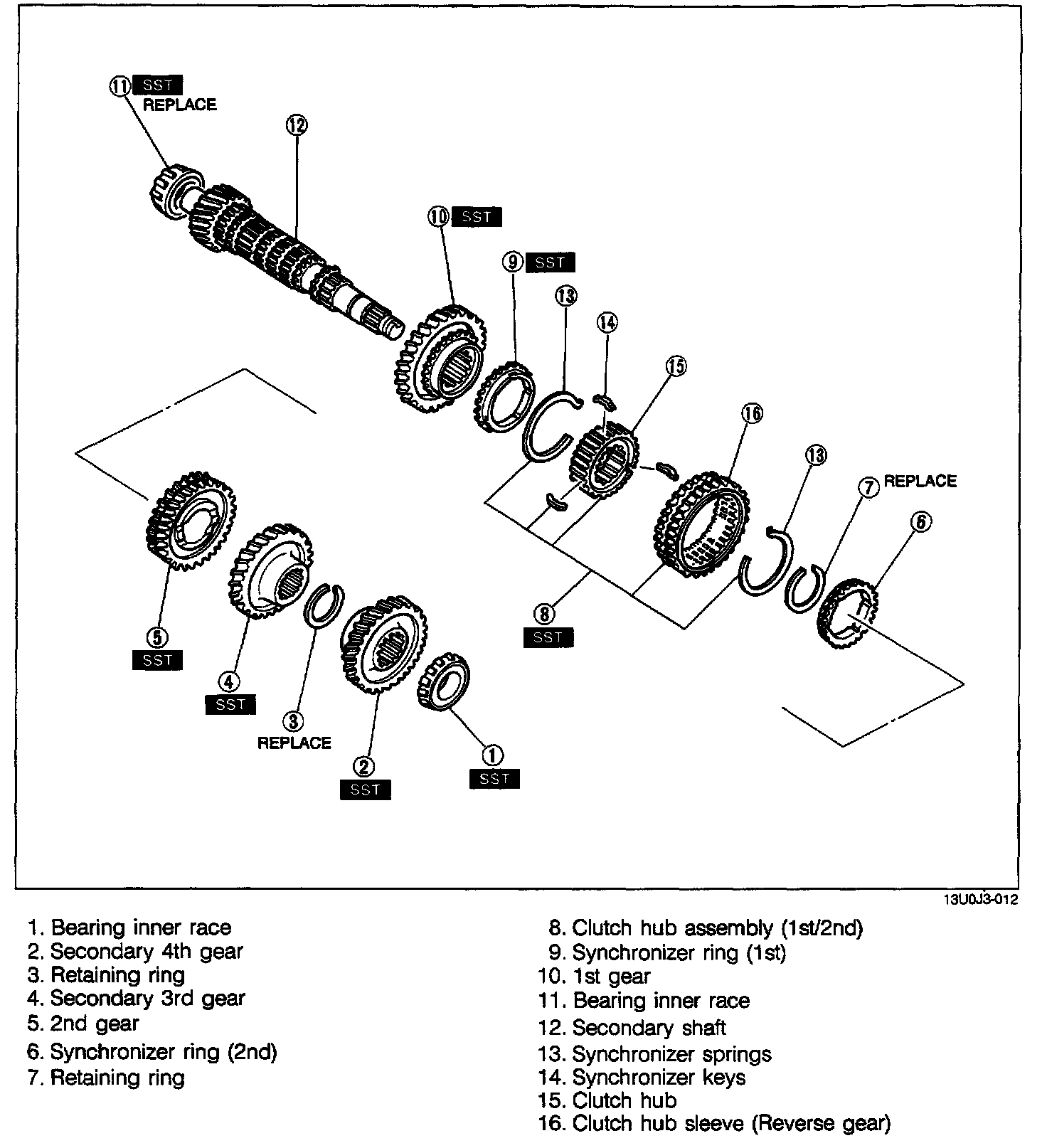
Secondary Shaft Assembly
1. Measure the thrust clearance of all gears before disassembly, referring to Preinspection.
2. Disassemble in the order shown in the image, referring to Disassembly Note.
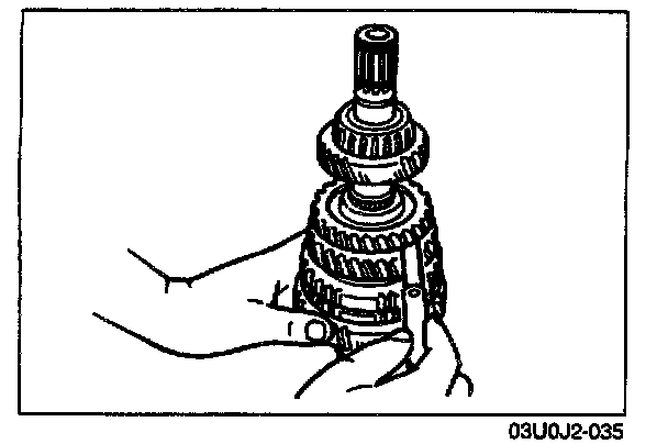
Preinspection
Thrust clearance
1. Measure the clearance between the 2nd gear and secondary 3rd gear.
Clearance: 0.175 - 0.455 mm (0.0069 - 0.0179 in.)
Maximum: 0.505 mm (0.0199 in.)
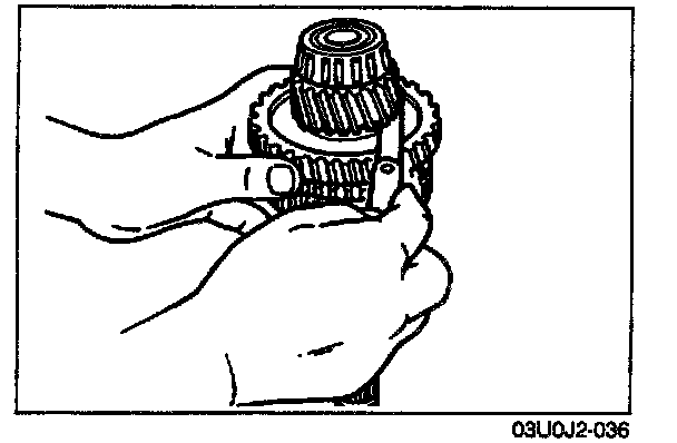
2. Measure the clearance between the 1st gear and differential drive gear.
Clearance: 0.05 - 0.28 mm (0.002 - 0.011 in.)
Maximum: 0.33 mm (0.0130 in.)
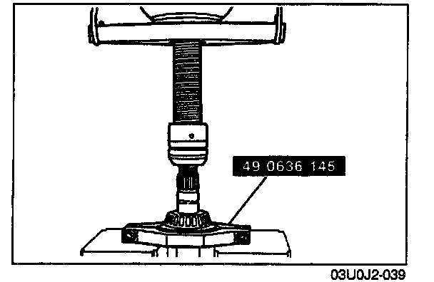
Disassembly note
Bearing inner race and secondary 4th gear
CAUTION: Hold the shaft with one hand so that It does not fall.
1. Remove the bearing inner race and secondary 4th gear with the SST.
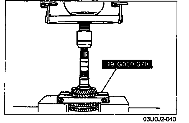
Secondary 3rd gear and 2nd gear
1. Remove the retaining ring.
2. Shift the gears to 1st gear.
CAUTION: Hold the shaft with one hand so that it does not fall.
3. Remove the secondary 3rd gear and 2nd gear with the SST.
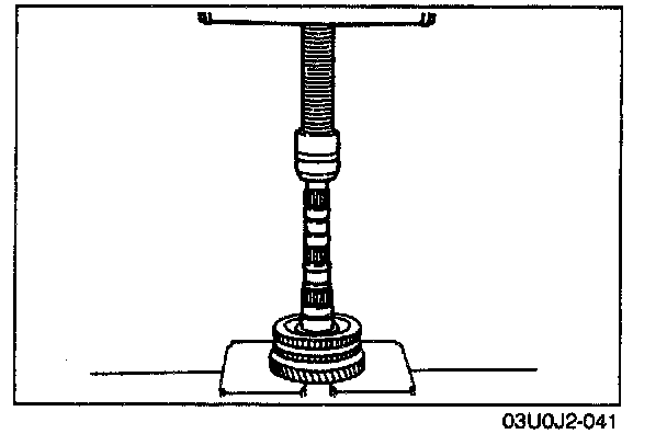
Clutch hub assembly (1st/2nd), synchronizer ring (1st), and 1st gear
1. Remove the retaining ring.
CAUTION: Hold the shaft with one hand so that it does not fall.
2. Remove the clutch hub assembly (1st/2nd), synchronizer ring (1st), and 1st gear with a press.
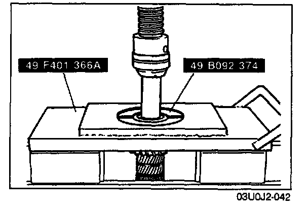
Bearing inner race (Secondary shaft end)
CAUTION: Hold the shaft with one hand so that it does not fall.
1. Remove the bearing inner race with the SST.
Front and Center Differential Assembly
1. Disassemble in the order shown in the image, referring to Disassembly Note.
2. Inspect all parts and repair or replace as necessary.
3. Inspect all bearings for damage and rough rotation, and replace as necessary.
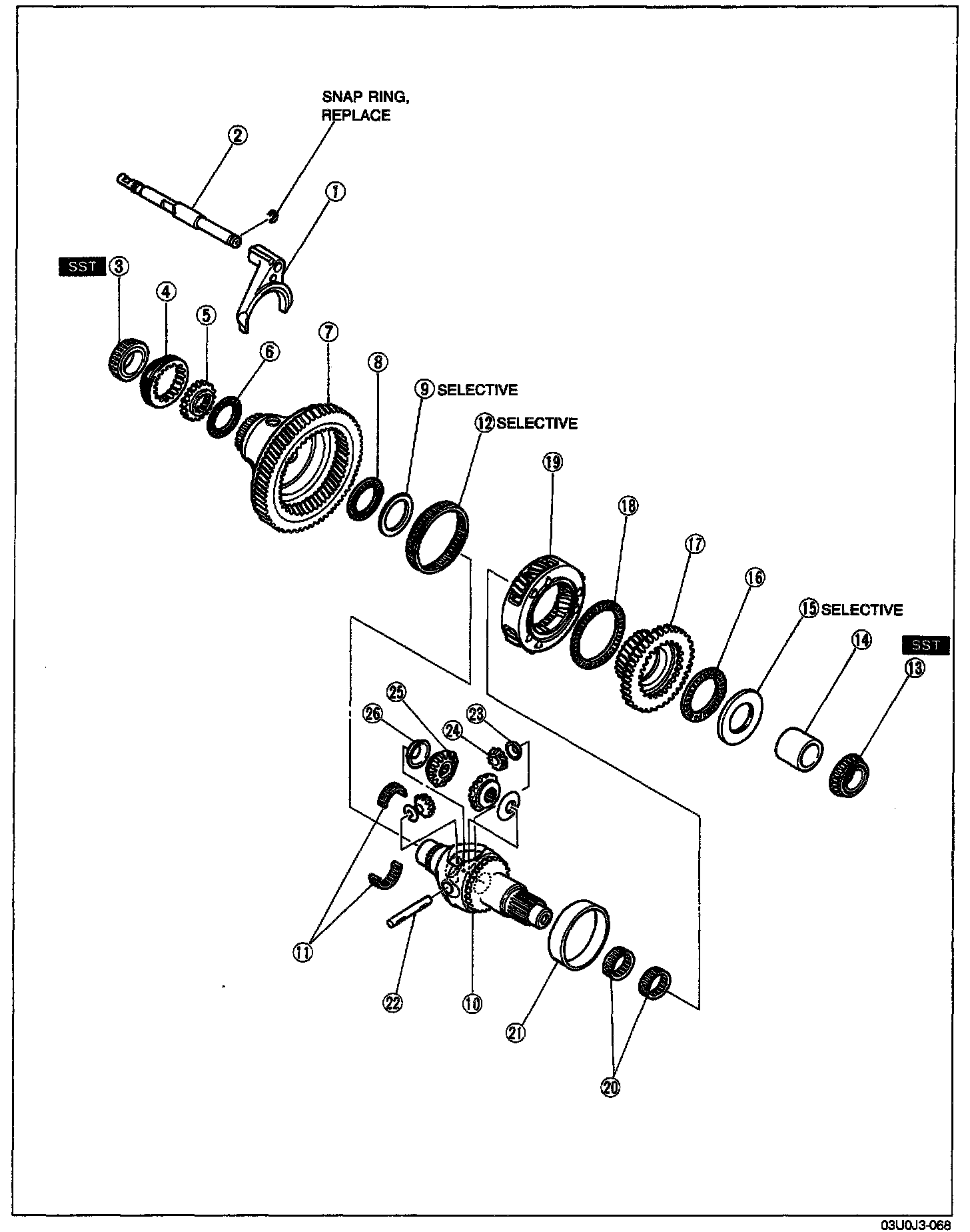
1. Center differential lock shift fork
2. Center differential look shift rod
3. Bearing inner race (Gear sleeve side)
4. Differential lock gear sleeve
5. Differential lock hub
Inspect for damage and wear
6. Gear case needle bearing
7. Ring gear case
Inspect gear teeth for wear and cracks
8. Gear case needle bearing
9. Differential lock thrust washer
10. Front differential gear case
11. Gear case needle bearings
12. Gear case needle bearing
13. Bearing inner race (Sun gear side)
14. Spacer
15. Thrust washer
16. Gear case needle bearing
17. Sun gear
Inspect gear teeth for wear and cracks
18. Gear case needle bearing
19. Planetary carrier
Inspect gears for wear, cracks and rough rotation
20. Gear case needle bearings
21. Differential gear case sleeve
22. Pinion shaft
23. Washers
24. Pinion gears
Inspect gear teeth for wear and cracks
25. Side gears
Inspect gear teeth for wear and cracks
26. Washers
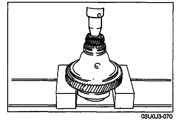
Disassembly note
Bearing inner race (Differential lock gear sleeve side)
CAUTION: Hold the front differential gear case with one hand so that it does not fall.
1. Remove the bearing inner race.
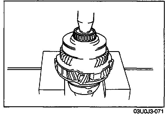
Bearing inner race (Sun gear side)
CAUTION: Hold the front differential gear case with one hand so that it does not fall.
1. Remove the bearing inner race.
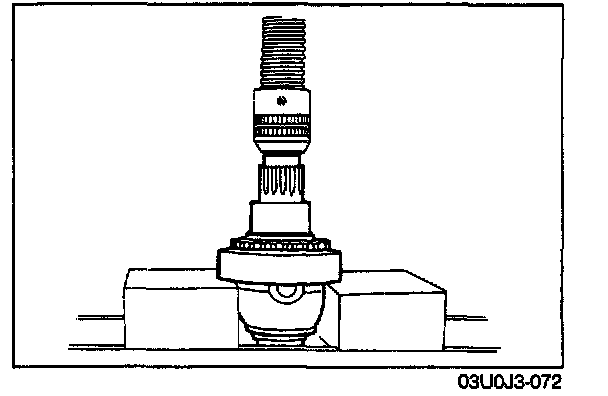
Differential gear case sleeve
CAUTION: Hold the front differential gear case with one hand so that it does not fall.
1. Remove the gear case sleeve with a press.
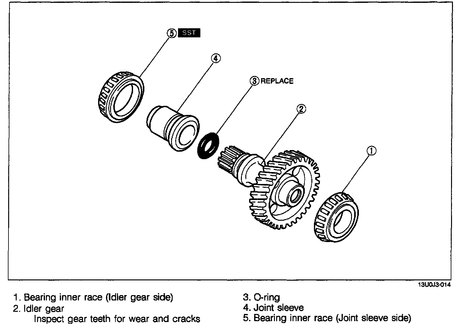
Idler Gear Assembly
1. Disassemble in the order shown in the image, referring to Disassembly Note.
2. Inspect all parts and repair or replace as necessary.
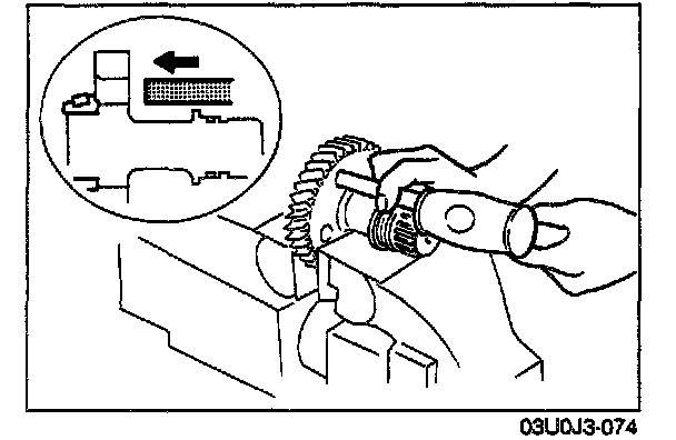
Bearing inner race (Idler gear side)
1. Fit a punch through a hole in the idler gear and tap off the bearing inner race.
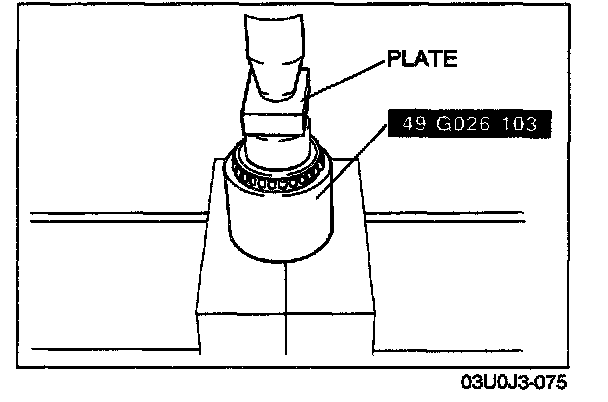
Bearing inner race (Joint sleeve side)
CAUTION: Hold the shaft with one hand so that it does not fall.
1. Remove the bearing inner race with the SST.
Transfer Carrier Assembly
1. Disassemble in the order shown in the image, referring to Disassembly Note.
2. Inspect all parts and repair or replace as necessary.
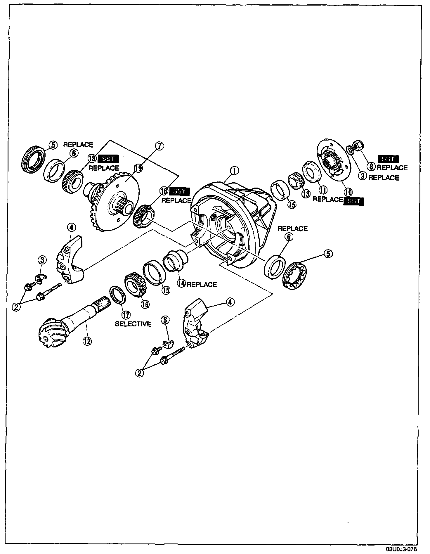
1. Transfer carrier
2. Bolts
3. Lock plates
4. Bearing caps
5. Adjusting screws
6. Bearing outer races (Side bearing)
7. Ring gear assembly
8. Nut
9. Washer
10. Companion flange
11. Oil seal
12. Drive pinion
13. Bearing inner race
Inspect for damage and rough rotation
14. Collapsible spacer
15. Bearing inner race
Inspect for damage and rough rotation
16. Bearing inner race
Inspect for damage and rough rotation
17. Spacer
18. Bearing inner races (Side bearing)
19. Ring gear
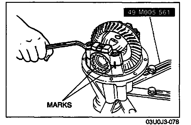
Disassembly note
Transfer carrier
1. Mark one bearing cap and the carrier for proper reassembly
Adjusting screw
1. Mark one adjusting screw and the carrier for proper reassembly.
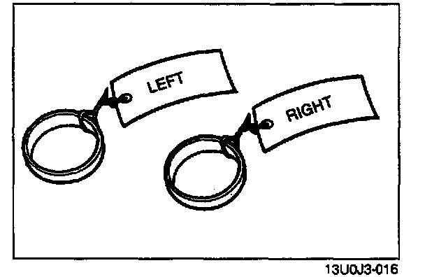
Bearing outer races (Side bearing)
NOTE: For proper reassembly, identify the bearing outer races.
1. Remove the bearing outer races.
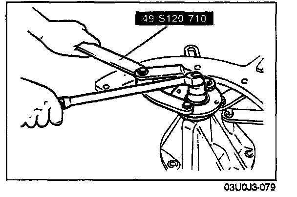
Nut
1. Hold the companion flange with the SST and remove the nut.
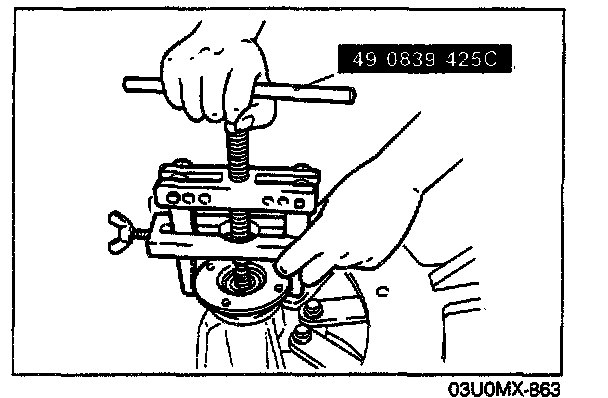
Companion flange
1. Remove the companion flange with the SST.
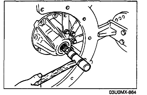
Drive pinion
1. Push out the drive pinion by attaching a miscellaneous nut to the drive pinion and tapping it with a copper hammer.
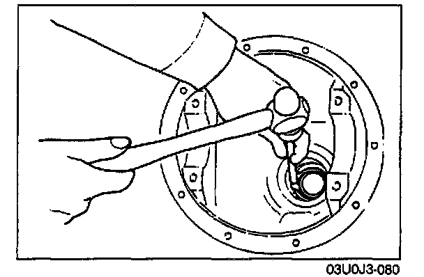
Bearing outer race
NOTE: Identify the bearing outer races for proper reassembly.
1. Remove the bearing outer races by alternately tapping the races at the two grooves in the carrier.
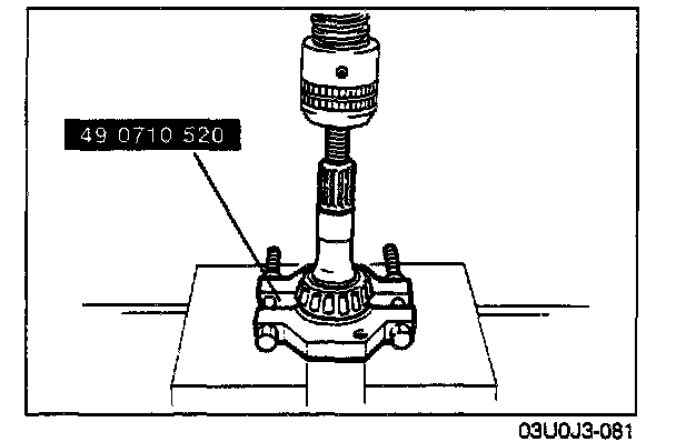
Bearing inner race (Drive pinion)
NOTE: Support the drive pinion by hand so that it does not fall.
1. Remove the bearing with the SST.
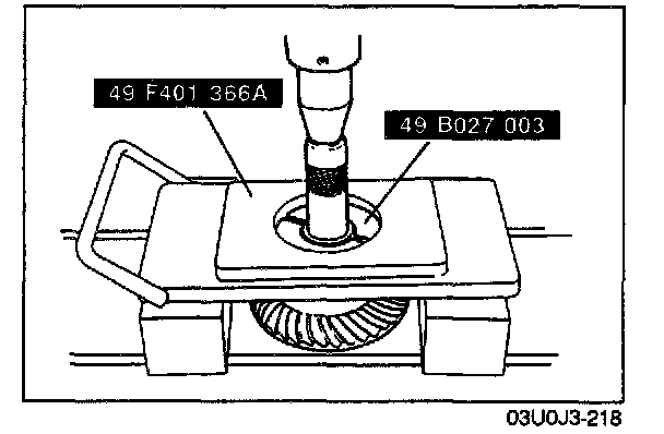
Bearing inner races (Side bearing)
NOTE: Support the ring gear by hand so that it does not fall.
1. Remove the bearing inner race with the SST.