Testing of Electrical Components, 4 Speed
Fig. 1 Mode switch terminal identification:
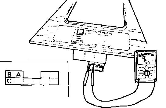
MODE SWITCH
Checking Continuity
1. Remove upper plate.
2. Disconnect mode switch connector.
3. Check continuity. In ``power'' mode, there should be continuity between terminals A and C, Fig. 1. In ``economy'' mode, there should be continuity between terminals A and B.
4. If continuity is not as described, replace mode switch. Otherwise, check terminal voltage.
Checking Terminal Voltage
1. Ensure continuity of switch is as previously described.
2. Reconnect mode switch connector.
3. Turn ignition switch to On position.
4. Check voltage between each terminal and ground. Voltage at terminal A should be below 1.5 volts in ``power'' and ``economy'' modes, or approximately 12 volts in ``hold'' mode. Voltage at terminal B should be below 1.5 volts in ``economy'' mode, or approximately 12 volts in `power'' and ``hold'' modes. Voltage at terminal C should be below 1.5 volts in ``power'' mode, or approximately 12 volts in ``economy'' and ``hold'' modes.
5. If voltage is not as described in ``power'' or ``economy'' mode, check wiring harness.
6. If voltage is not as described in ``hold'' mode, check 1A terminal of EC-AT control unit and the hold switch.
HOLD SWITCH
Checking Continuity
1. Remove upper plate.
2. Disconnect hold switch connector.
3. Check for continuity between terminals. There should be continuity when switch is released and there should be no continuity when switch is depressed.
4. If continuity is not as described, replace hold switch. If continuity is as described, check terminal voltage.
Checking Terminal voltage
1. Check continuity of switch as previously described.
2. Reconnect hold switch connector.
3. Turn ignition switch to On position.
4. Check voltage between terminal (yellow with blue stripe wire) and ground. Voltage should be below 1.5 volts with switch released, or approximately 12 volts with switch depressed.
5. If voltage is not as described, check wiring harness.
Fig. 2 Inhibitor switch terminal identification:
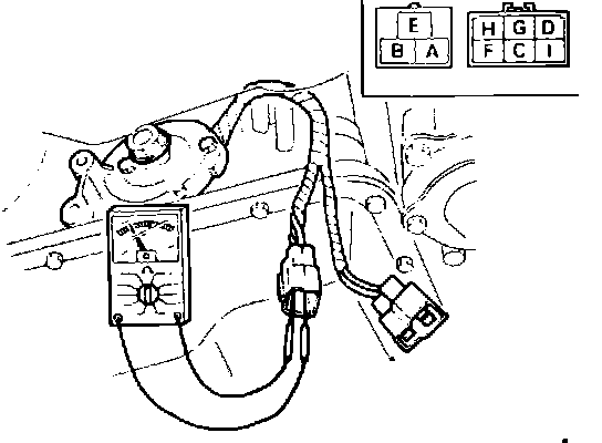
INHIBITOR SWITCH
1. Disconnect inhibitor switch connector.
2. Check continuity of terminals as follows, Fig. 2:
a. With selector lever in P position, there should be continuity between terminals A and B and between terminals C and D.
b. With selector lever in R position, there should be continuity between terminals C and E.
c. With selector lever in N position, there should be continuity between terminals A and B and between terminals C and F.
d. With selector lever in D position, there should be continuity between terminals C and G.
e. With selector lever in S position, there should be continuity between terminals C and H.
f. With selector lever in L position, there should be continuity between terminals C and I.
Fig. 3 Cruise control switch terminal identification:
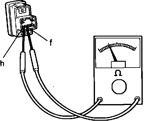
CRUISE CONTROL SWITCH
1. Using ohmmeter, check for continuity between terminals f and h, Fig. 3. There should be continuity with switch in Off position and no continuity with switch in On position.
2. If continuity is not as described, replace switch.
Fig. 4 Throttle sensor terminal identification:
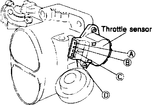
THROTTLE SENSOR
Variable Resistor
1. Disconnect throttle sensor connector from throttle sensor and connect ohmmeter between terminals A and D, Fig. 4.
2. Check resistance, which should be 3.5-6.5k ohms.
3. Connect ohmmeter between terminals B and D.
4. Gradually open throttle valve while checking resistance. Resistance should be below approximately 1k ohms with throttle valve fully closed, or approximately 3.5-6.5k ohms with throttle valve fully open.
5. If resistance is not as described, check throttle sensor adjustment.
Idle Switch
1. Disconnect throttle sensor connector from throttle sensor.
2. Connect an ohmmeter between terminals C and D, Fig. 4.
3. Check for continuity between terminals C and D with a feeler gauge inserted between throttle stopper screw and throttle valve lever. When a .02 inch (.5 mm) gauge is inserted, there should be continuity. When a .028 inch (.7 mm) gauge is inserted, there should be no continuity.
4. If continuity is not as described, loosen screws and rotate throttle sensor to adjust.
5. Tighten screws and seal them with white paint.
6. After checking and adjusting throttle sensor, connect throttle sensor connector.
KICKDOWN SWITCH
Checking Terminal Voltage
1. Turn ignition switch to On position.
2. Check voltage of terminal V. With accelerator pedal depressed at least 7/8 of its travel, voltage should be approximately 12 volts. With pedal depressed less than 7/8 of its travel, voltage should be below 1.5 volts.
3. If voltage is not as described, check wiring harness or switch, or adjust switch position.
Checking Switch
1. Disconnect kickdown switch connector.
2. Using ohmmeter, check continuity of switch. There should be continuity when switch is depressed and no continuity when switch is released.
3. If continuity is not as described, replace kickdown switch.
TURBINE SENSOR
Checking Resistance
1. Disconnect turbine sensor connector.
2. Check resistance at terminals.
3. If resistance is not approximately 245 ohms, check voltage generation of sensor.
Checking voltage Generation
1. Remove turbine sensor.
2. Connect voltmeter to terminals.
3. Wave tip of turbine sensor approximately .197 inch (5 mm) away from a magnet.
4. If sensor does not generate voltage, replace it.
Fig. 5 EC-AT 16 pin connector terminal 1P location:
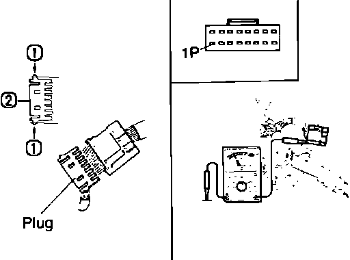
SPEED SENSOR
1. Disconnect 16 pin connector from from EC-AT control unit.
2. Remove plug from connector.
3. Connect voltmeter between terminal 1P and ground, Fig. 5, then turn ignition switch to On position.
4. Remove speedometer cable from transmission.
5. Slowly turn speedometer cable one turn.
6. If approximately 7 volts does not show 4 times, check combination meter.
Fig. 6 Solenoid valve connector terminal identification:
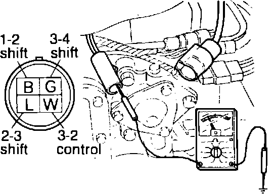
SOLENOID VALVE (1-2 SHIFT, 2-3 SHIFT, 3-4 SHIFTS, 3-2 CONTROL)
Checking Resistance
1. Disconnect solenoid valve connector.
2. Check resistance between each terminal and ground, Fig. 6.
3. If resistance is not 13-27 ohms, check wiring harness for open or short circuit and replace solenoid valve(s) as necessary.
Fig. 7 EC-AT 20 pin connector terminals 2K, 2M, 2O & 2P locations:
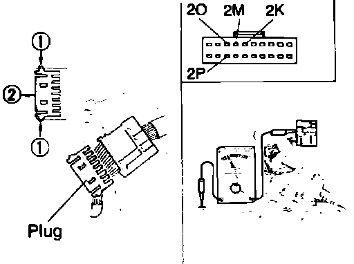
Checking Continuity
1. Disconnect 20 pin connector from EC-AT control unit.
2. Remove plug from connector.
3. Check continuity between terminals 2K, 2M, 2O and 2P and ground, Fig. 7.
4. If there is no continuity, check wiring harness for open circuit.
SOLENOID VALVE (LOCKUP CONTROL)
Checking Resistance
1. Disconnect solenoid valve connector.
2. Check resistance between terminals.
3. If resistance is not 13-25 ohms, replace solenoid valve.
Fig. 8 EC-AT 20 pin connector terminal 2N location:
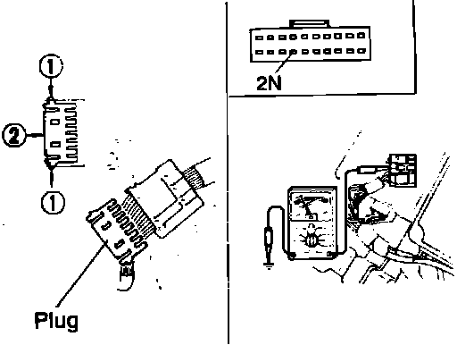
Checking Continuity
1. Disconnect 20 pin connector from EC-AT control unit.
2. Remove plug from connector.
3. Check continuity between terminal 2N and ground, Fig. 8.
4. If there is no continuity, check wiring harness for open circuit.
EC-AT CONTROL UNIT
Checking Solenoid Transistor
1. Disconnect connectors from EC-AT control unit.
2. Check continuity between terminals 2K, 2M, 2N, 2O, and 2P, and terminal 2S.
3. If there is no continuity at any terminal, replace EC-AT control unit.
Fig. 9a EC-AT control unit terminal voltage chart (Part 1 of 2):
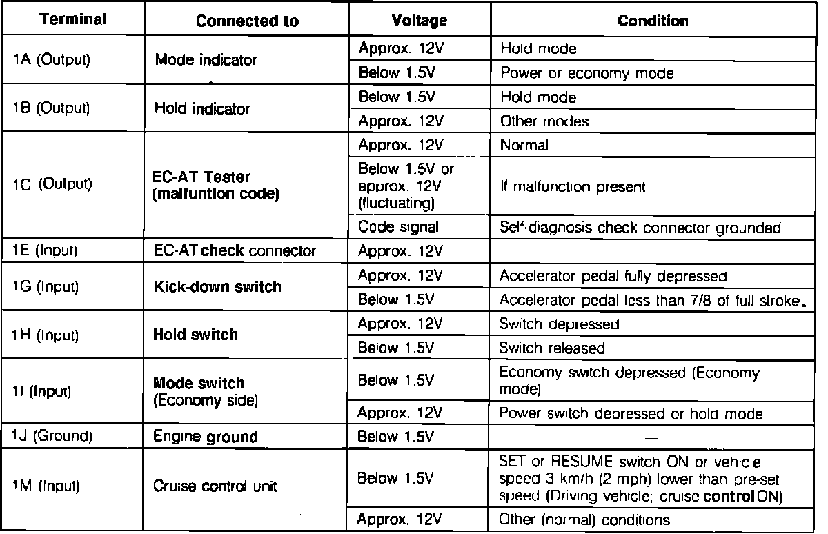
Fig. 9b EC-AT control unit terminal voltage chart (Part 2 of 2):
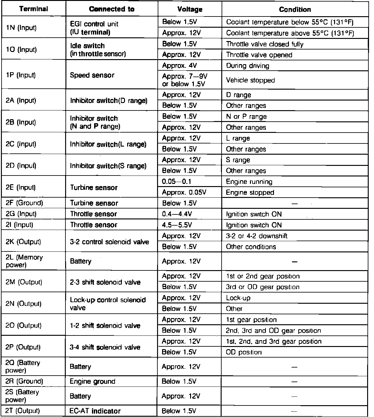
Checking Terminal Voltage
Check voltage at terminal, Fig. 9.