Selector Lever Knob, Boot And Bezel
Selector Lever Knob, Boot and Bezel
This is a "Trustmark Authoring Standards (TAS) Repair Procedure"
- TAS style procedures can be identified by steps that have no accompanying step text and the magenta color of the electrical connectors and fasteners such as nuts, bolts, clamps or clips.
- TAS removal and installation procedures use a sequence of color illustrations to indicate the order to be followed when removing/disassembling or installing/assembling a component.
- Many of the TAS procedures will have the installation information within the removal steps.
- The TAS color illustrations use a variety of symbols to indicate important details of the procedures. It is important to understand these symbols in order to properly used the TAS procedures.
Refer to How to Use TAS Procedures and TAS Symbol Glossary at Vehicle | Description and Operation for additional information on these TAS procedures.
For additional information, refer to How to Use TAS Procedures How to Use TAS Procedures
Removal
NOTE:
Make sure that the selector lights function correctly. If the ribbon cable is damaged it will be necessary to remove the floor console to access the ribbon cable connector on the selector lever assembly.
1 Position the gearshift lever in NEUTRAL.
2 Switch the ignition off.
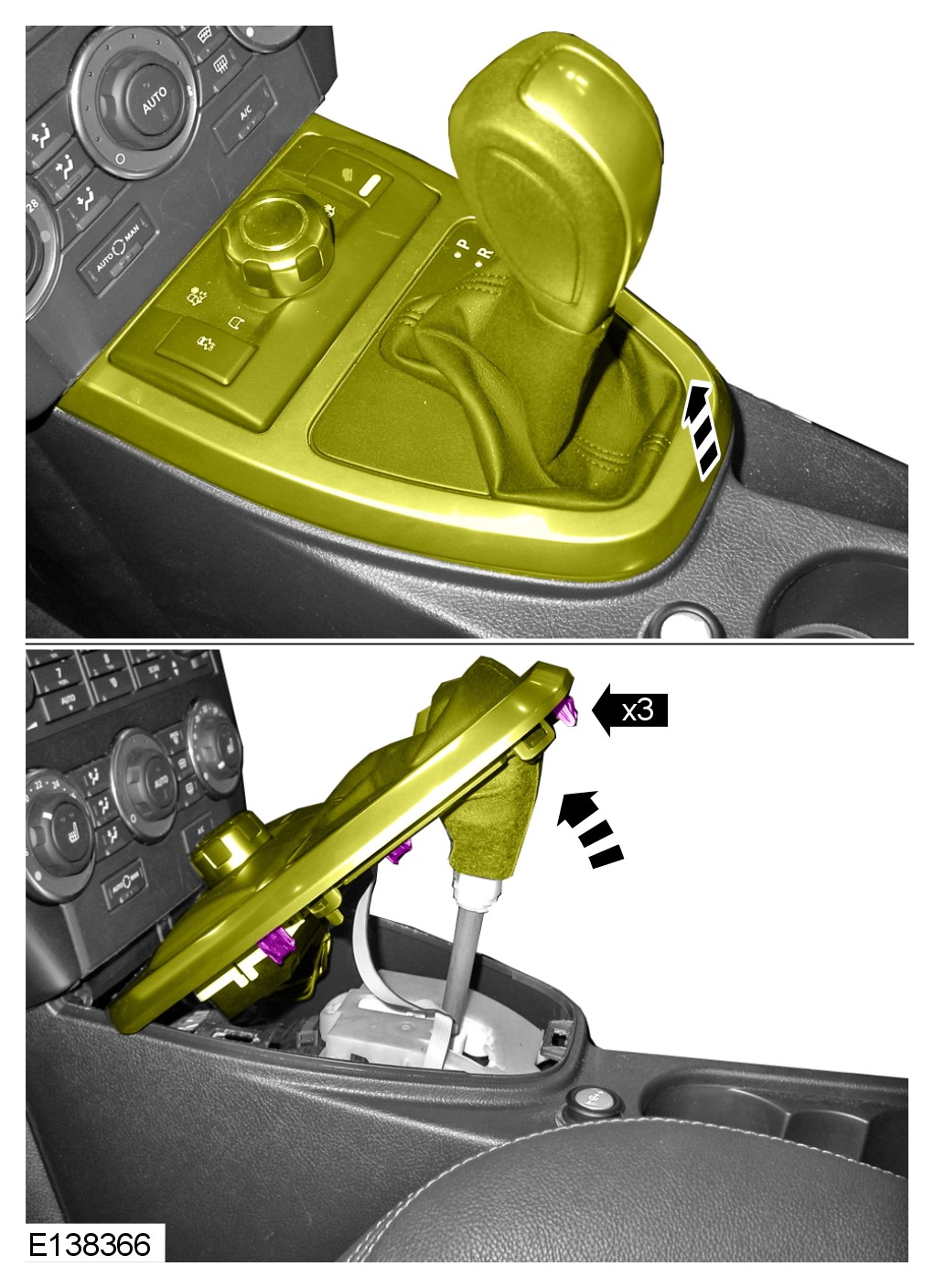
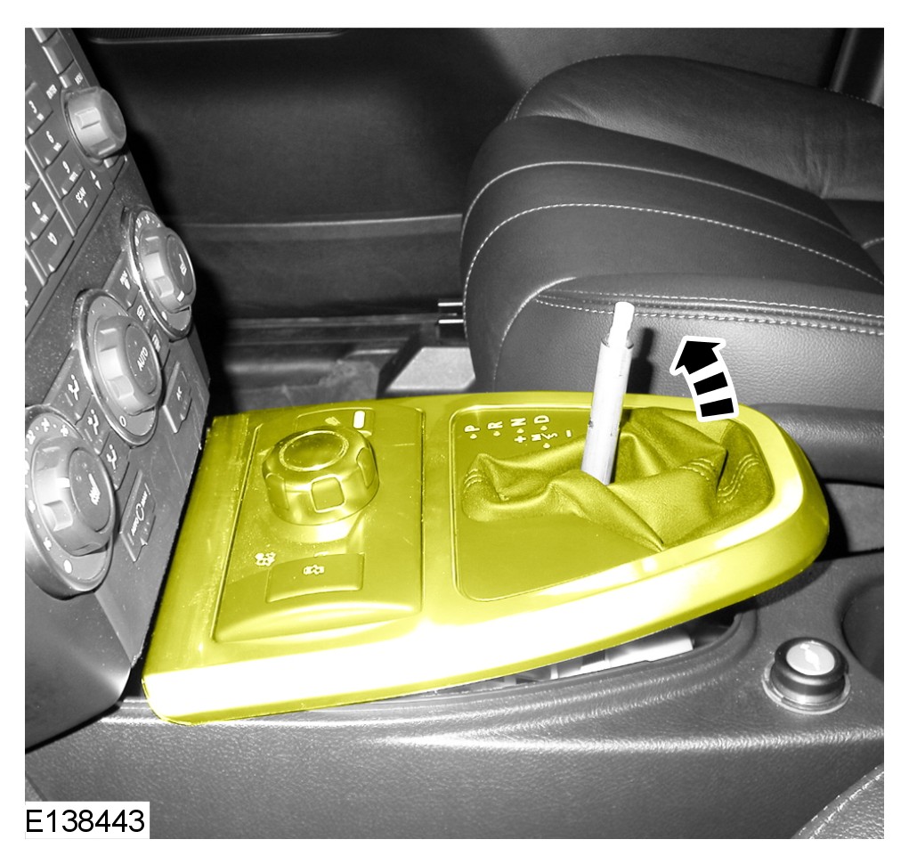
Release the gear lever surround by pulling upwards firmly at the rear.
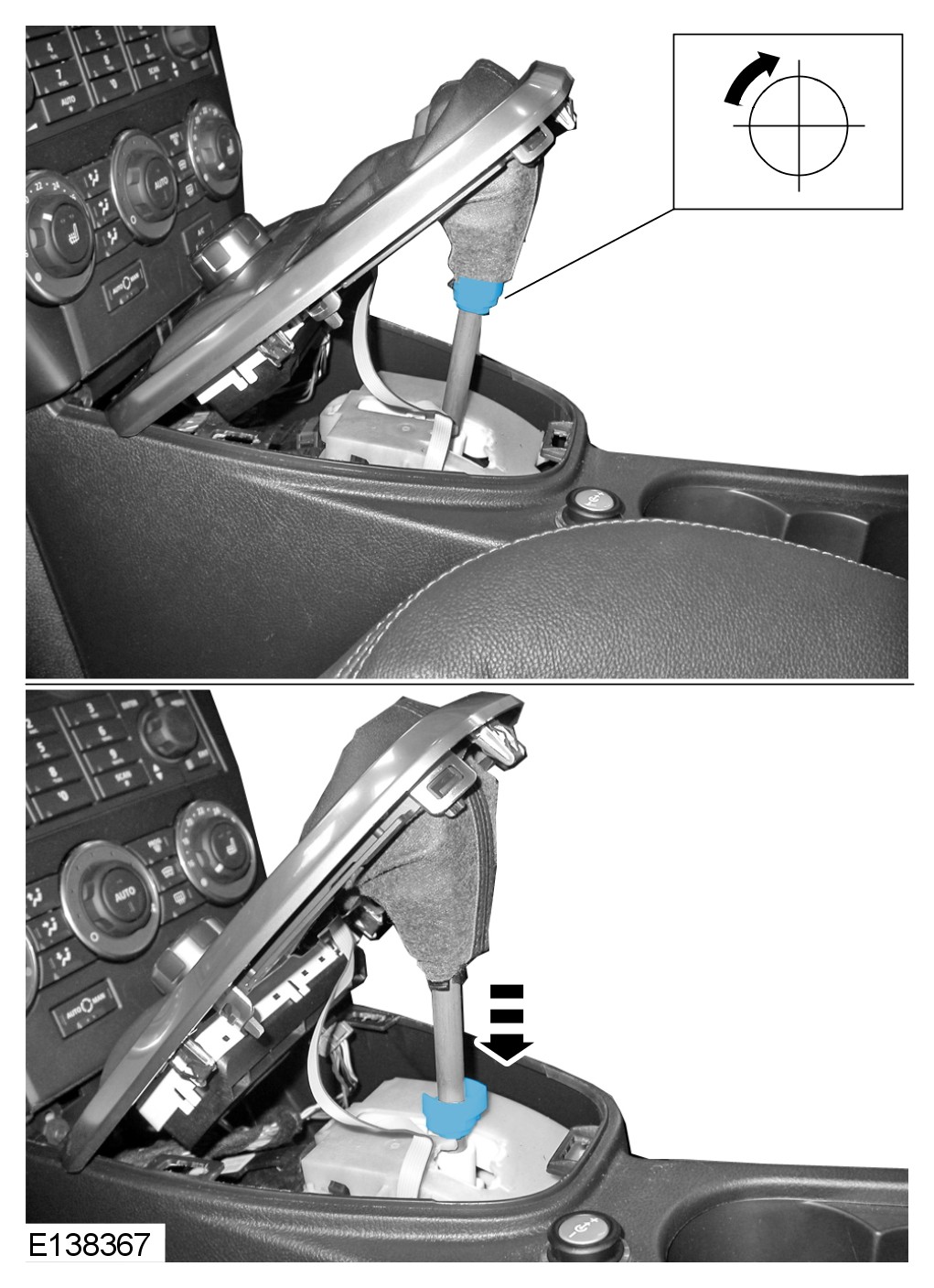
Release the locking ring.
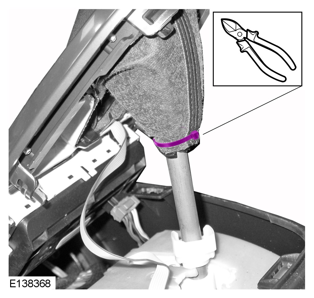
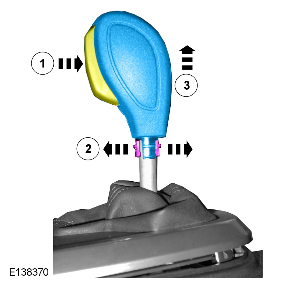
WARNING: The selector lever knob will be released suddenly, keep face clear during removal.
CAUTION: Make sure the selector lever button is depressed when removing the selector lever knob. Failure to follow this instruction may result in damage to the selector lever assembly.
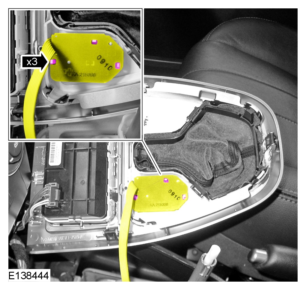
CAUTION: Take care not to touch the printed side of the printed circuit board (PCB).
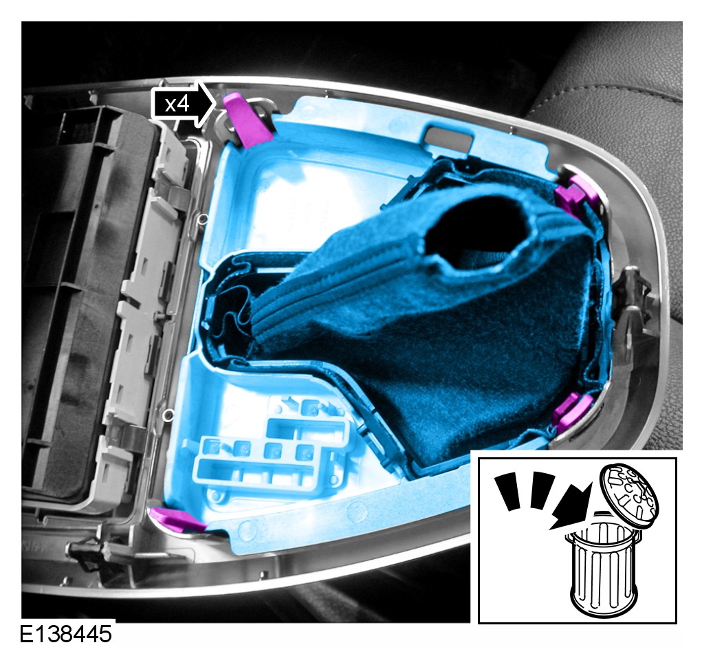
CAUTION: Discard the component.
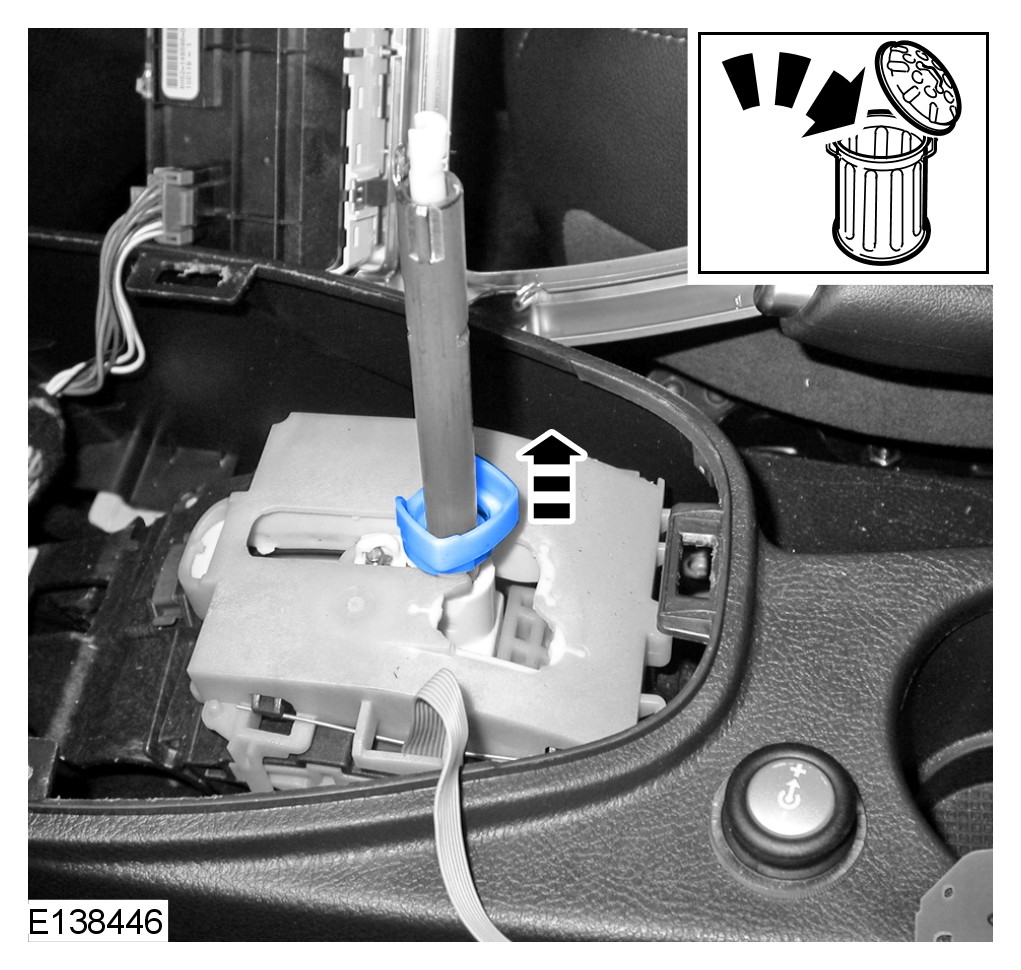
CAUTION: Discard the component.
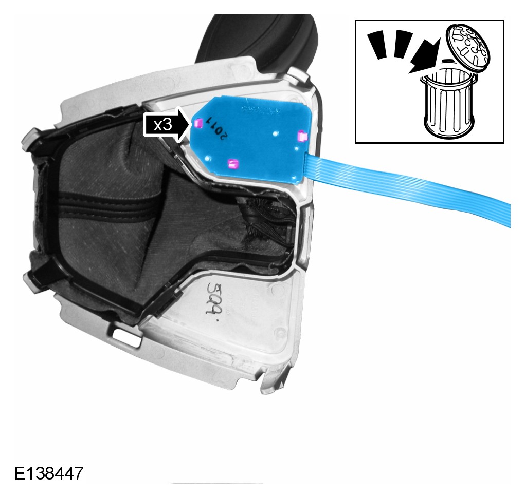
CAUTION: Discard the component.
3 Remove and discard the selector lever assembly printed circuit board.
Installation
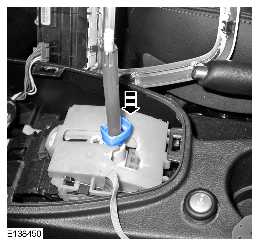
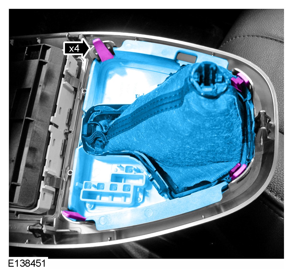
CAUTION: Take care not to touch the printed side of the printed circuit board (PCB).
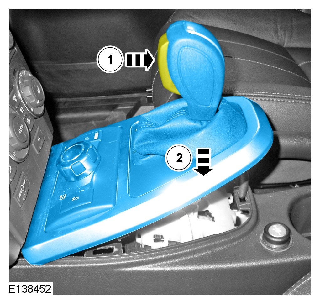
CAUTION: Make sure the selector lever button is depressed when installing the selector lever knob. Failure to follow this instruction may result in damage to the selector lever assembly.
CAUTION: Make sure the ribbon cable is routed in front of the selector shaft.
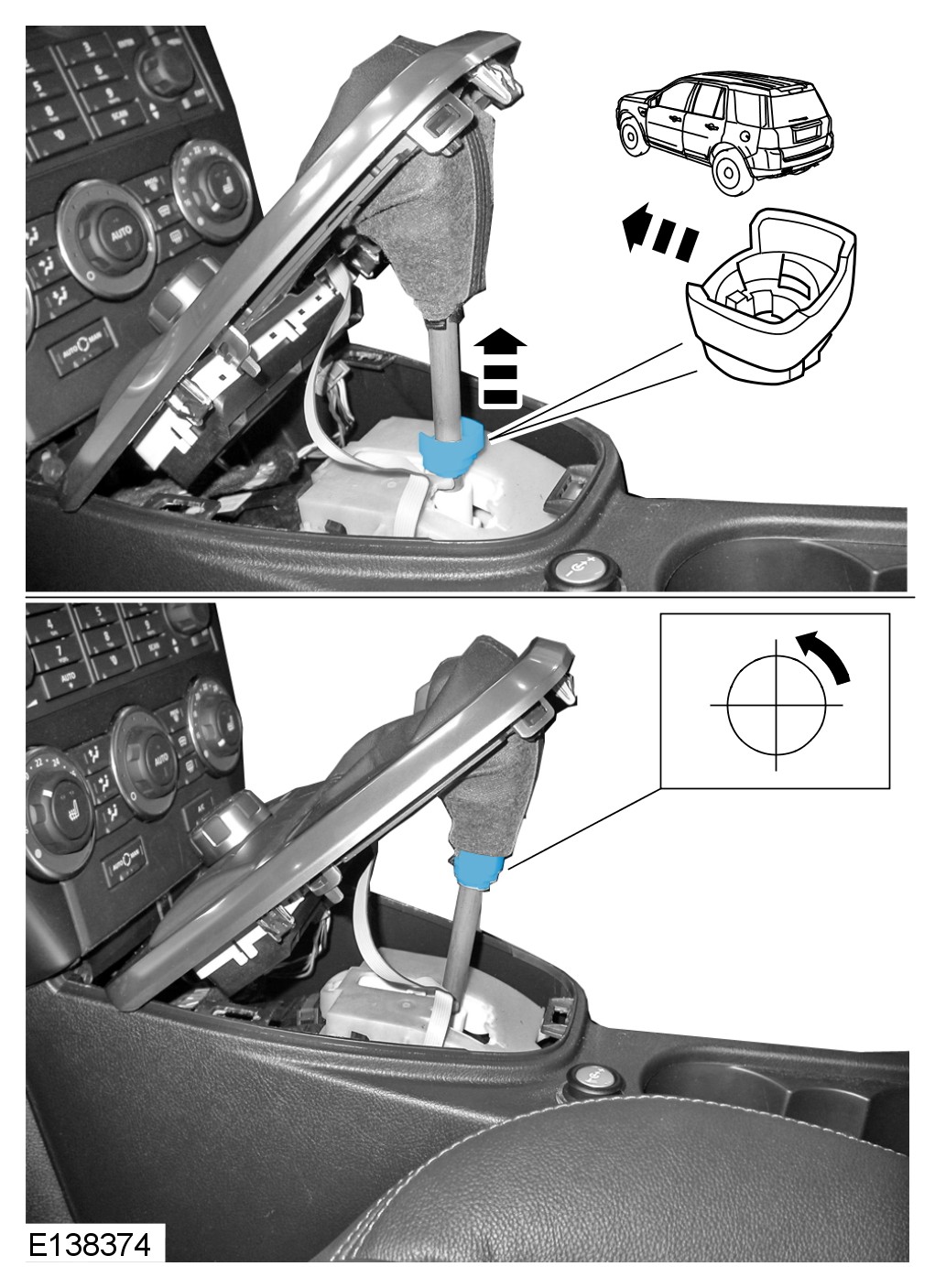
NOTE:
Make sure the cut out on the locking ring faces towards the front of the vehicle.
Install the locking ring.
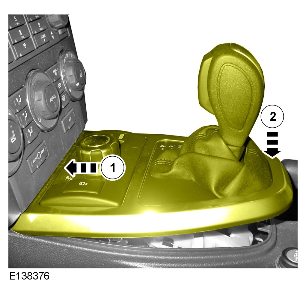
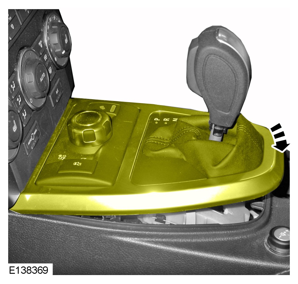
Secure into the 3 clips.
1 Switch the ignition on.
2 Position the transmission selector lever into PARK.