Audio System - Poor Radio Reception
NUMBER: JTB00083(Issue 1)
MODEL: XK
DATE: 28 FEB 2008
SECTION: 415
Poor Radio Reception - Repair Procedure
AFFECTED VEHICLE RANGE:
XK (X150) VIN: B15632 - B25813
Model Year: 2008 ONLY
CONDITION SUMMARY:
POOR RADIO RECEPTION - AM / FM FREQUENCIES
Situation:
An issue has been identified where there may be poor radio reception on the AM and FM frequencies. There may also be a concern of being able to hear some vehicle generated noises on some frequencies. This could be caused by the 120 ohm coaxial cable weakening the signal strength to the concealed antenna.
Action:
Should a customer express the above concern, follow the Repair Procedure to install a 50 ohm coaxial cable and reconfigure the Audio Front Control Module as outlined in this bulletin.

PARTS
TOOLS:
IDS DVD 111 Patch File / or later and Midtronics PSC-550 Vehicle Power Supply

WARRANTY:
NOTE:
Repair procedures are under constant review, and therefore times are subject to change; those quoted here must be taken as guidance only. Always refer to DDW to obtain the latest repair time.
DDW requires the use of causal part numbers. Labor only claims must show the causal part number with quantity of zero
REPAIR PROCEDURE
INSTALLING THE 50 OHM COAXIAL CABLE OVERLAY HARNESS
NOTE:
Global Technical Reference (GTR) lookup sequence is as follows:
GTR Home> NAS > Service Information > Workshop Manuals > New XK Workshop Manual>501: Body and Paint
1. Remove the trunk lid lower trim panel (see Global Technical Reference GTR Workshop Manual, section 501-05).
CONVERTIBLE ONLY
2. Release clips and remove the luggage compartment lid trim panel.
ALL MODELS
3. Remove the rear seat backrest (see Global Technical Reference GTR Workshop Manual, section 501-10).
4. Remove the right-hand side rear quarter trim panel (see Global Technical Reference GTR Workshop Manual, section 501-05).
5. Remove the floor console finish panel for access only (see Global Technical Reference GTR Workshop Manual, section 501-12).
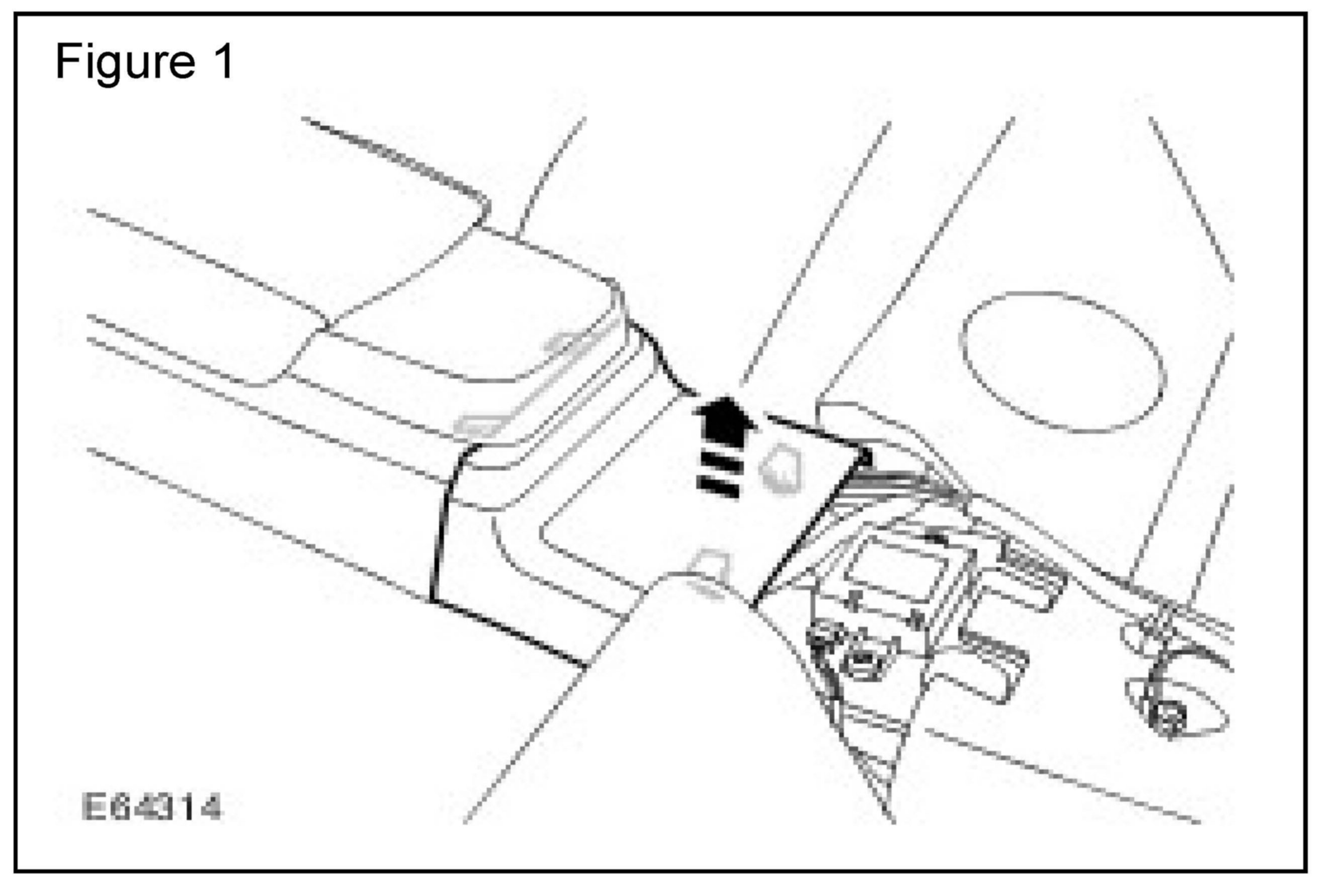
6. Remove the floor console rear panel by carefully releasing the two clips. (Figure 1)
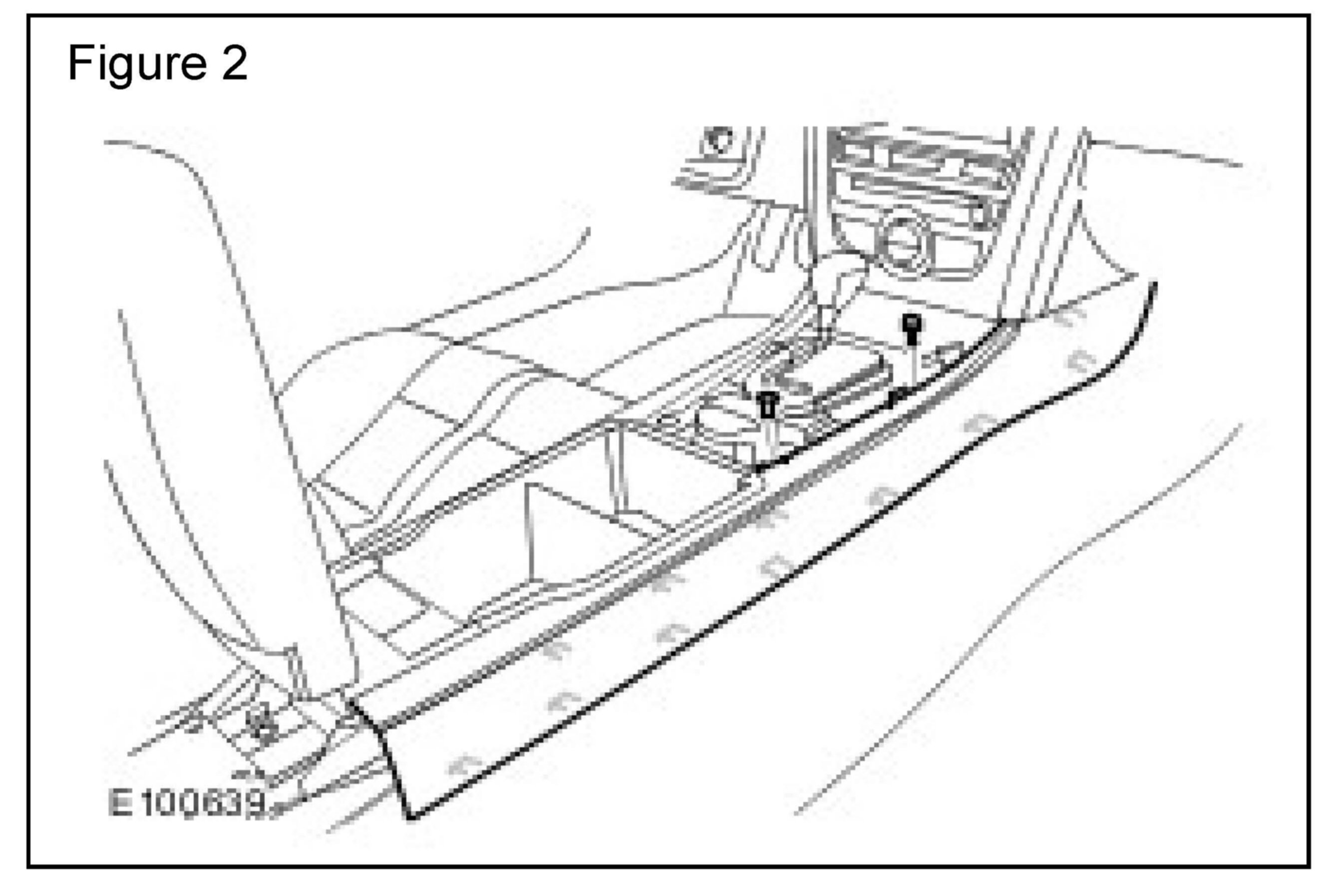
7. Remove the right-hand floor console side panel trim by removing the two Torx bolts and releasing the 11 clips. (Figure 2)
NOTE:
Global Technical Reference (GTR) lookup sequence is as follows:
GTR Home> NAS > Service Information> Workshop Manuals> New XK Workshop Manual > 419: Electronic Feature Group
8. Remove the navigation system display module (see Global Technical Reference GTR Workshop Manual, section 419-07).
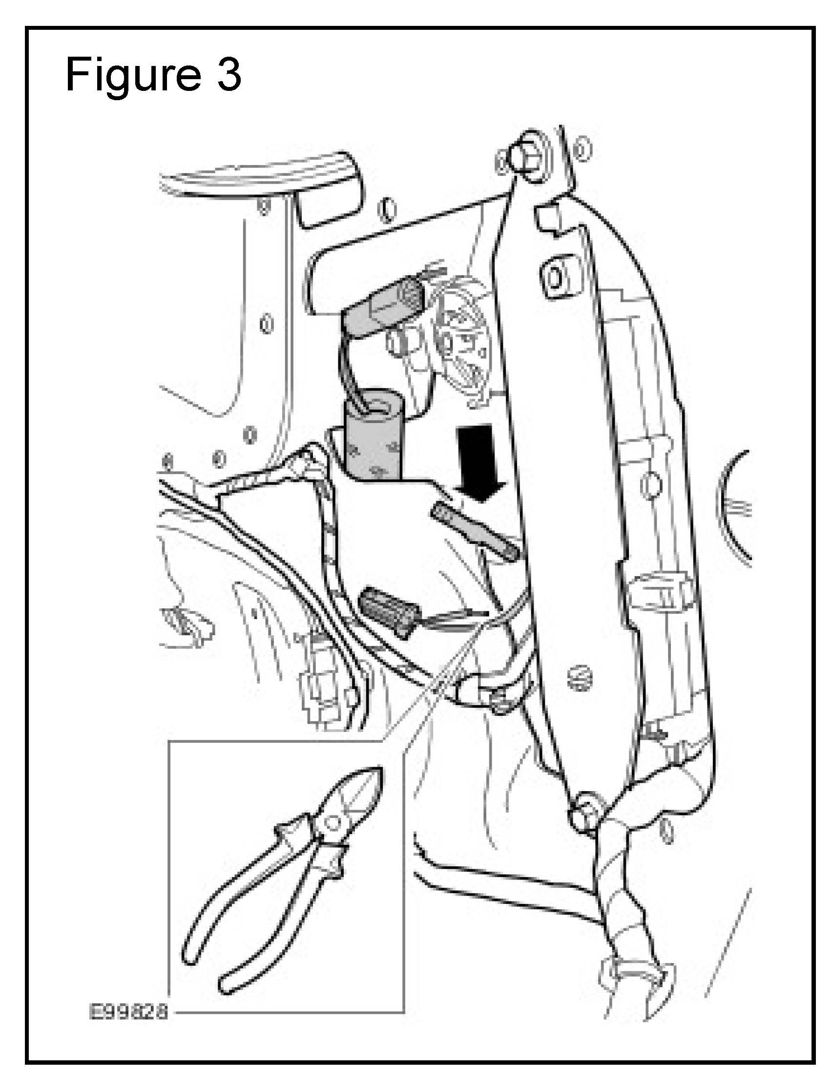
9. Splice the new ground lead into the black/green ground wire in the trunk lid harness. (Figure 3)
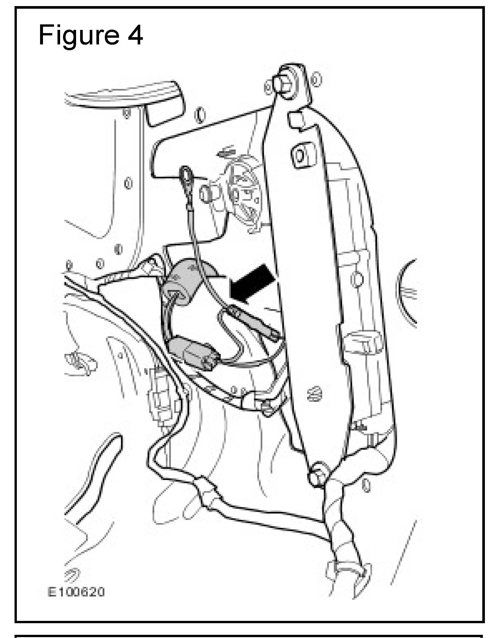
10. Insulate trunk lid harness using cloth tape. (Figure 4)
NOTE:
The ground lead eyelet is installed beneath the bracket.
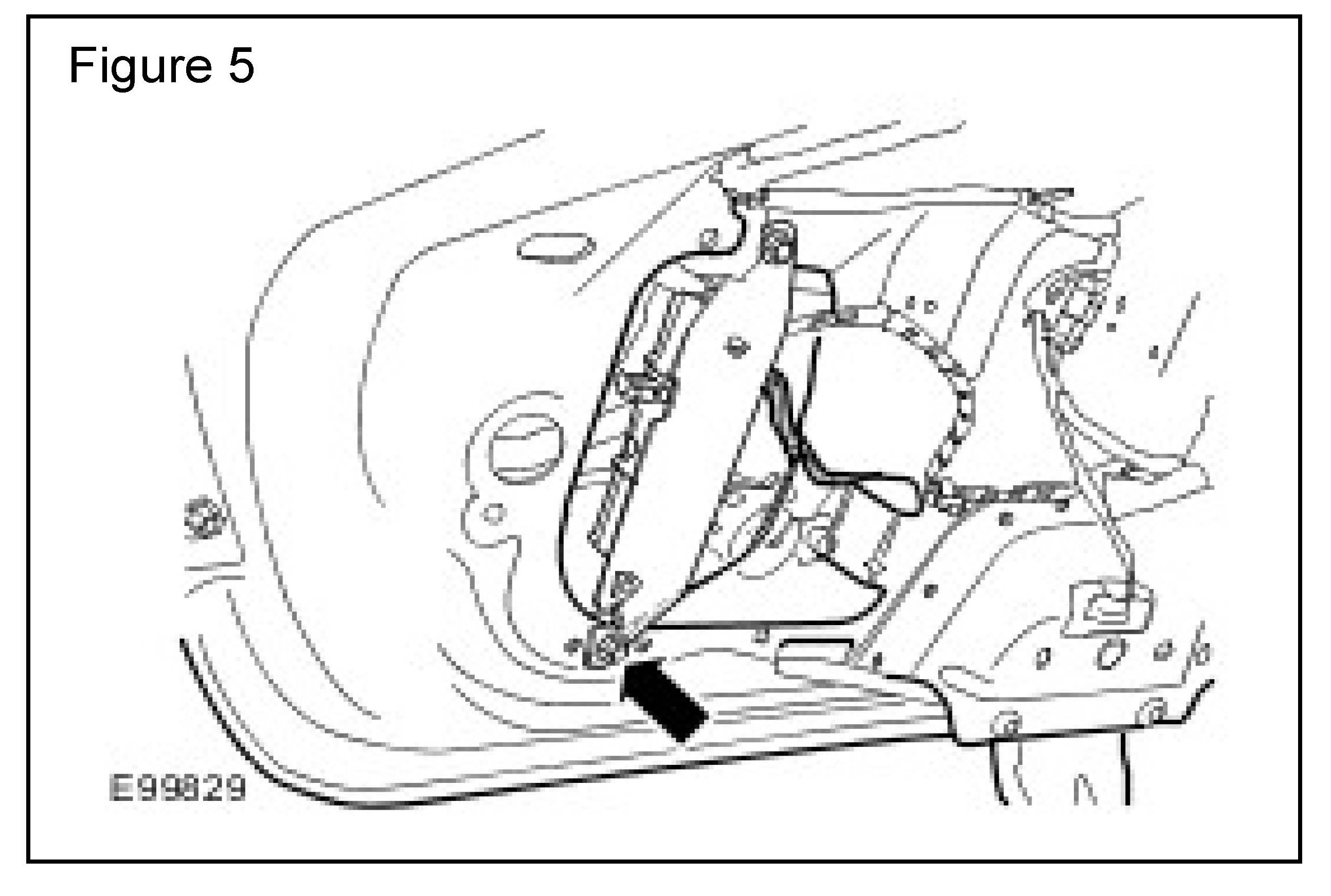
11. Install the antenna ground lead to the trunk lid and tighten the bolt to 12 Nm (8.8 Lbf-ft). (Figure 5)
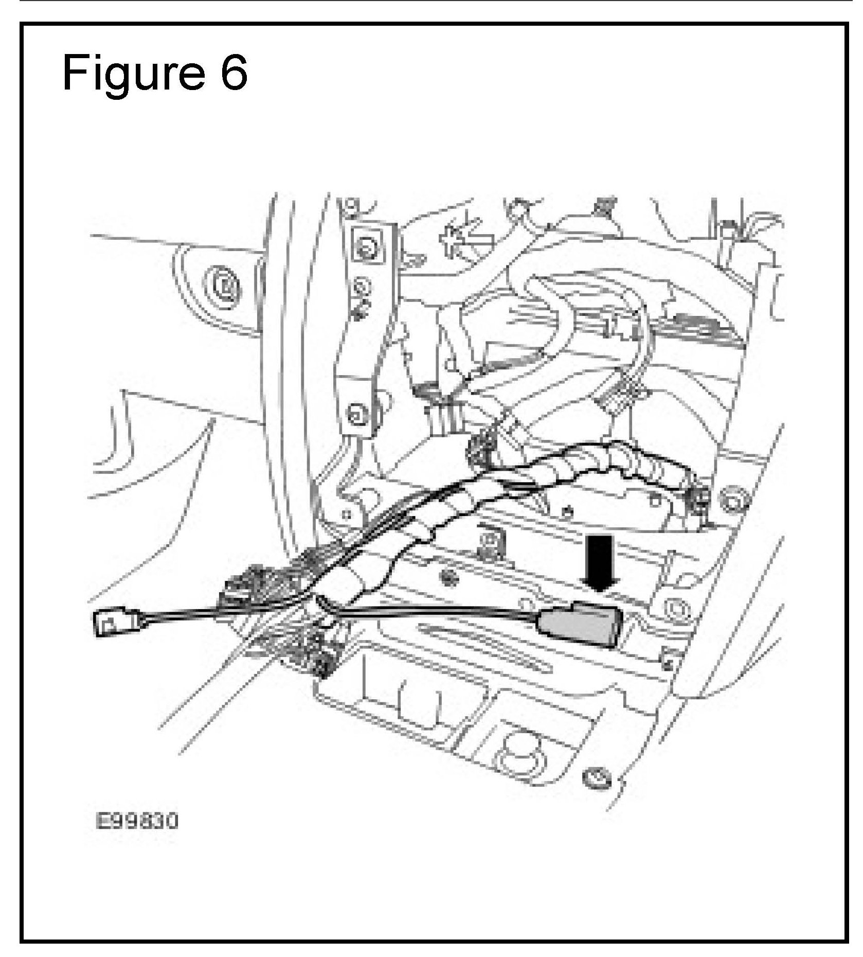
12. Install the front antenna overlay lead (C2P 17261 - part of kit) to the vehicle, using cloth tape to secure the antenna lead to the existing vehicle harness. (Figure 6)
NOTE:
Ensure the old coaxial cable connectors are removed. The old cable is the thickest.
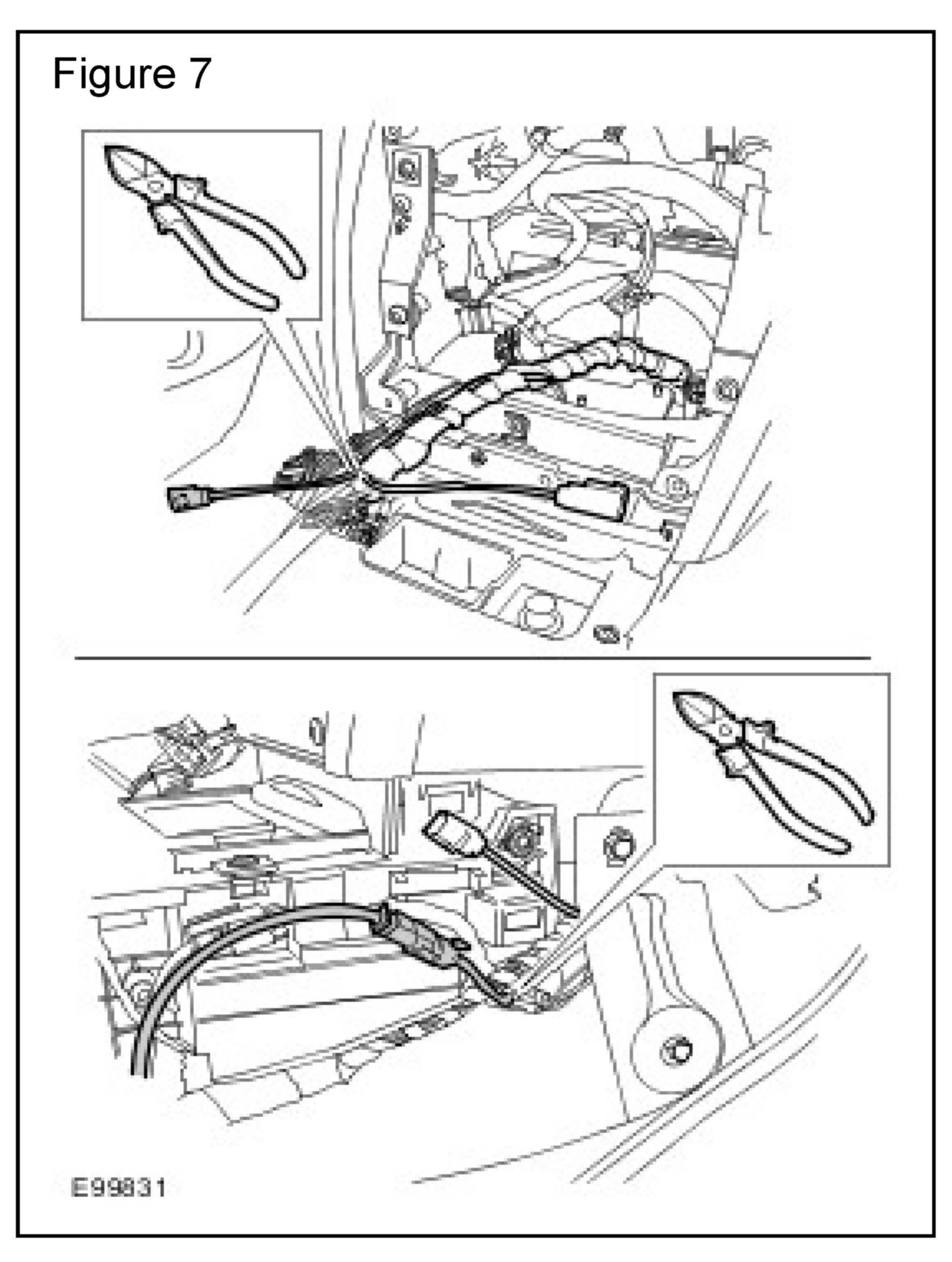
13. Remove the original front antenna lead connectors. (Figure 7)
CONVERTIBLE ONLY
14. Remove the three bolts to release the convertible top hydraulic pump and position to one side.
ALL MODELS
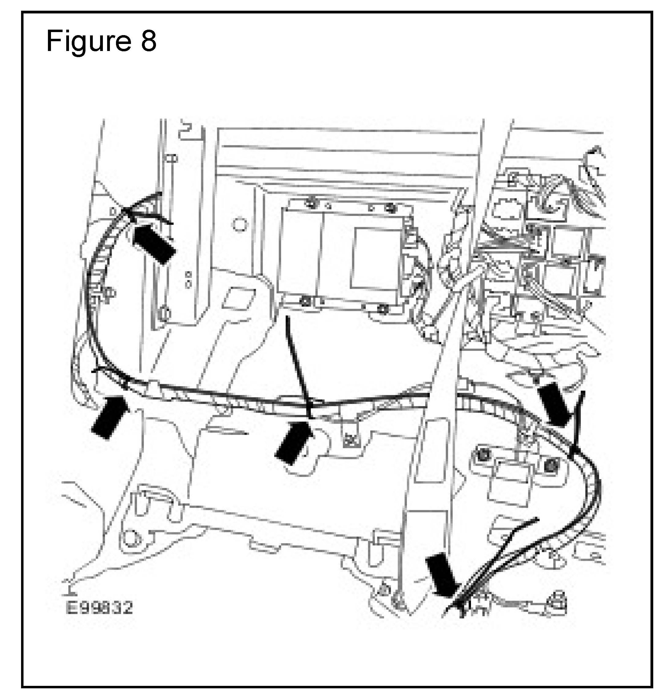
15. Using cable ties to secure to existing passenger compartment harness, install the center antenna overlay lead (C2P 17264 - part of kit). (Figure 8)
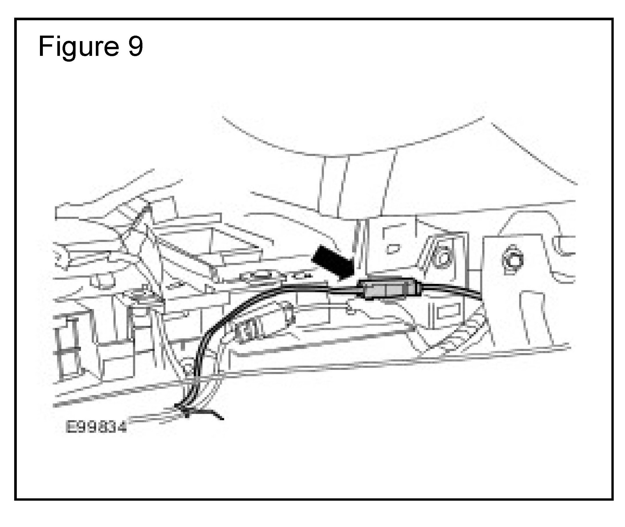
16. Connect the new center antenna overlay lead to the new front antenna lead. (Figure 9)
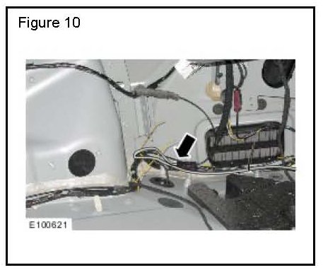
17. Connect the new center antenna overlay lead to the new front antenna lead (located at the right-hand side of the luggage compartment) harness. (Figure 10)
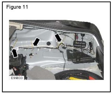
18. Secure the center antenna overlay lead to the luggage compartment harness using cable ties. (Figure 11)
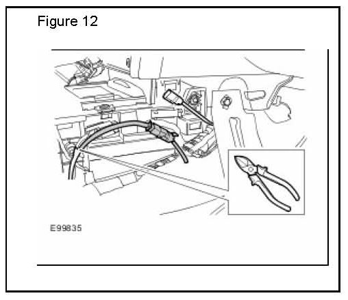
19. Remove the original center antenna lead connectors. (Figure 12)
20. Remove the original rear antenna lead connectors.
CONVERTIBLE ONLY
21. Install the convertible top hydraulic pump.
ALL MODELS
22. Install the navigation system display module (see Global Technical Reference GTR Workshop Manual, section 419-07).
23. Verify radio operation.
24. Install the right-hand floor console side panel trim (Figure 13):
^ Carefully align and secure the clips.
^ Tighten the Torx screws to 6 Nm (4.4 Lbf ft).
25. Install the floor console rear panel:
^ Align the lugs and secure the clips.
26. Install the floor console finish panel (see Global Technical Reference GTR Workshop Manual, section 501-12).
27. Install the right-hand side rear quarter trim panel (see Global Technical Reference GTR Workshop Manual, section 501-05).
28. Install the rear seat backrest (see Global Technical Reference GTR Workshop Manual section 501-10).
29. Install the trunk lid lower trim panel (see Global Technical Reference GTR Workshop Manual, section 501-05).
CONVERTIBLE ONLY
30. Align the clips and install the luggage compartment lid trim panel.
RECONFIGURING THE AUDIO FRONT CONTROL MODULE:
VIN B15632 TO B24583; 2008MY ONLY
CAUTION:
This procedure requires IDS DVD111 with patch file 1 or later loaded and the Midtronics PSC-550 Vehicle Power Supply.
1. Connect a Midtronic battery conditioner/power supply to the vehicle.
2. Connect IDS to the vehicle and begin a new diagnostic session by entering the correct VIN for the current vehicle.
3. Follow the IDS prompts to read the vehicle configuration.
4. Select NO when prompted Do you wish to read diagnostic trouble codes?.
5. Press 'tick' to continue.
6. Select the Vehicle Configuration tab when the Content Model is displayed.
7. Select Module Programming from the Vehicle Configuration menu.
8. Select Configure Existing Module from the drop-down menu.
9. Select Software Enhancement program from the drop-down menu.
10. Select Infotainment System from the drop-down menu.
11. Select 'Audio Front Control Module' from the drop-down menu.
12. Press 'tick' to continue.
13. Follow all on-screen instructions to complete this task.
14. Exit the current session when the task is completed.
15. Disconnect IDS and the battery charger/power supply.

Disclaimer