Reinstallation Procedure Information
REINSTALLATION PROCEDUREReinstall the field coil in the reverse order to the removal procedure. The coil flange protrusion must match the hole in the front of the housing to prevent coil movement. Correctly locate the field coil lead. Support the compressor on the four mounting tabs at the rear of the compressor. If using a vice, clamp on the mounting tabs - NOT ON THE COMPRESSOR BODY.
FIGURE 12:
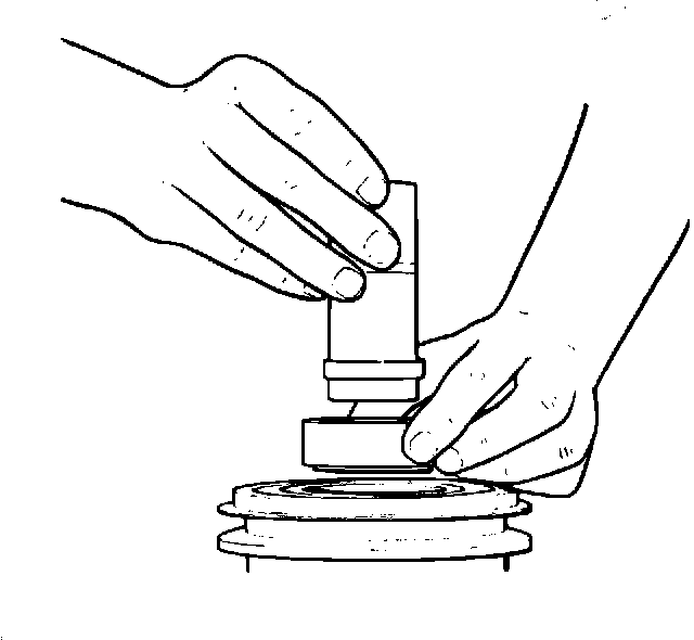
FIGURE 13:
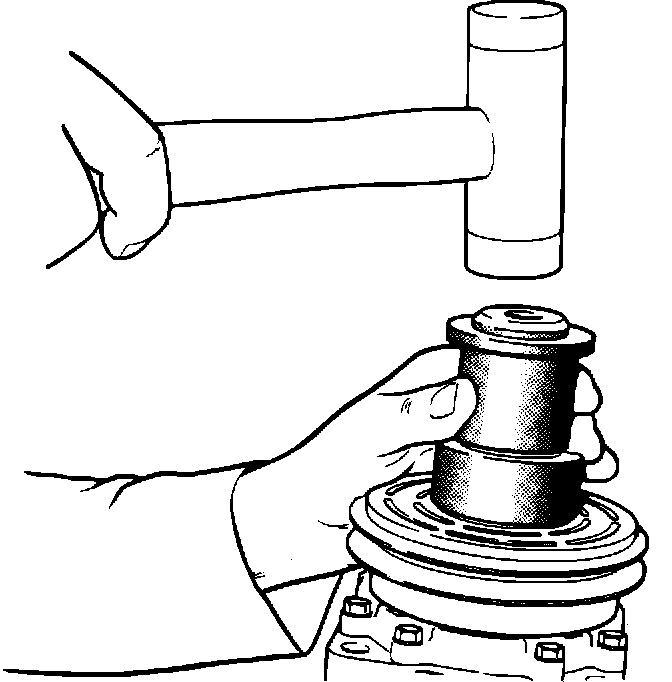
Align the rotor assembly squarely on the front housing hub. Using the rotor installer set, place the ring part of the set into the bearing cavity. Make certain the outer edge rests firmly on the rotor bearing outer race. Place the tool set driver into the ring (Fig. 12). With a hammer, tap the end of the driver while guiding the rotor to prevent binding. Tap until the rotor bottoms against the compressor front housing hub, (Fig. 13). Refit the internal bearing circlip using pinch type circlip pliers. Refit the external front housing circlip using spread type circlip pliers.
Check that the original clutch shims are in place on the compressor shaft. Replace the compressor shaft key. Align the front plate to compressor shaft key. Using a shaft protector, tap the front plate onto the shaft until it has bottomed onto the clutch shims.
FIGURE 14:
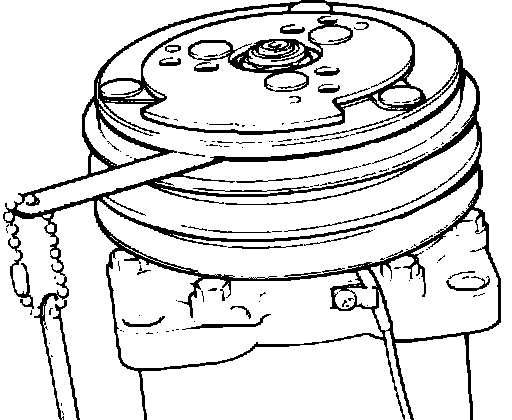
Refit the shaft nut and torque to 25-30 ft.lbs. Check the air gap with a 0.016-0.031 in. feeler gauge (Fig. 14). If the gap is not consistent around the circumference, lightly tap down at the maximum gap and gently pry up at the minimum gap.
NOTE: The air gap is determined by the spacer shims. When fitting a new clutch assembly, try the original shims first. Add or subtract shims if the air gap does not meet the above specifications.
FIGURE 15:
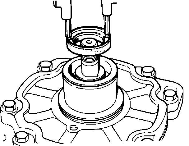
FIGURE 16:
SHAFT SEAL - RENEW
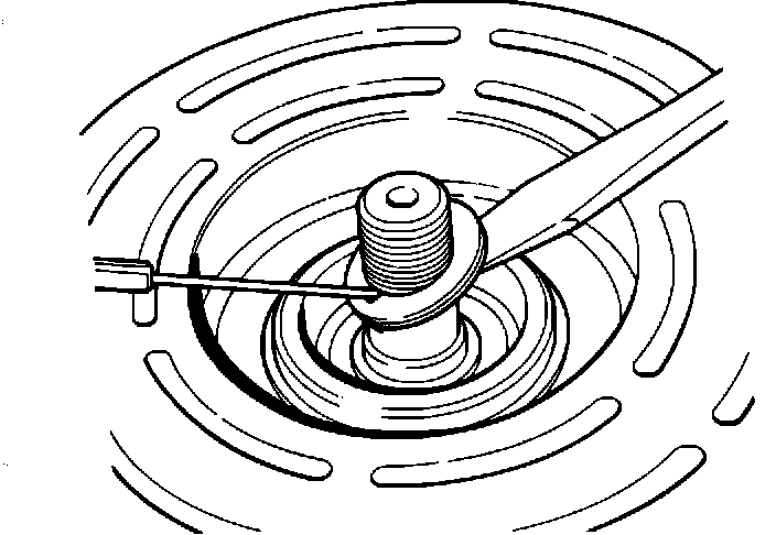
Remove the clutch as previously described. Using circlip pliers, insert the points into the two holes of the felt ring metal retainer and lift out the felt ring (Fig. 15). Remove the clutch shims. Use O-ring hook and a small screwdriver (Fig. 16) to prevent shims from binding on the shaft.
FIGURE 17:
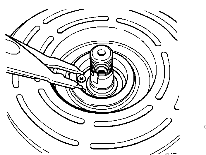
FIGURE 18:
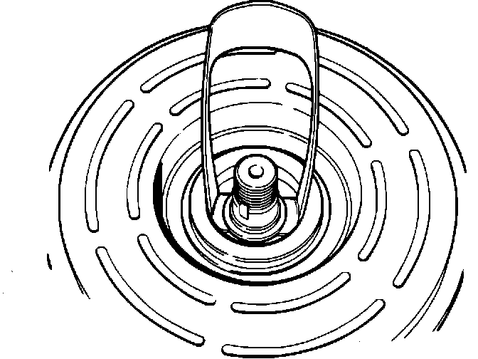
Remove the shaft seal seat retaining circlip using pinch type circlip pliers (Fig. 17). Remove the shaft seal seat by using the tongs, JD 147, (Fig. 18).
FIGURE 19:
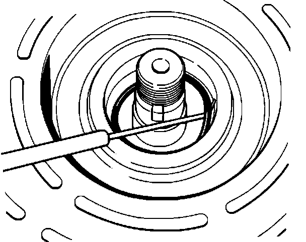
Use the O-ring hook to remove the shaft seal O-ring. Take care not to damage the groove (Fig. 19).
FIGURE 20:
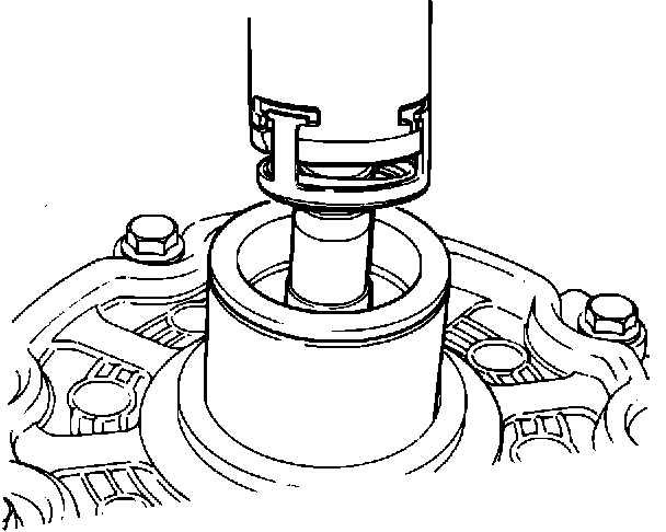
Insert the seal remover and installer tool, JD 150, against the seal assembly. Press down against the seal spring and twist the tool until feeling it engage in the slots of the seal cage. Lift out the seal assembly (Fig. 20).
FIGURE 21:
INSTALLING
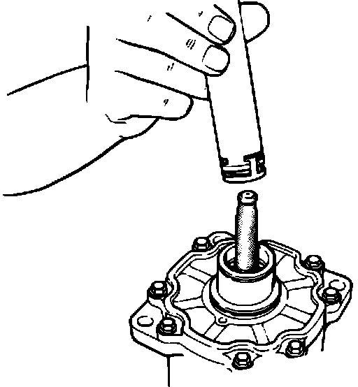
Clean the seal cavity thoroughly with R12 vapor. Clean thoroughly with a lint free or synthetic cloth and clean refrigerant oil. Then blow out with R12 pressurized vapor. Make sure all foreign substances are completely removed. Insert the seal sleeve protector, JD 148, over the compressor shaft. Do not touch the new seal lapping surface. Dip the mating surface in a clean refrigerant oil before proceeding. Engage the slots of the seal remover and installer to the new seal cage. Insert the seal assembly firmly into place in the compressor seal cavity, (Fig. 21). Twist the tool in the opposite direction to disengage the tool from the seal cage. Remove the tool.
FIGURE 22:
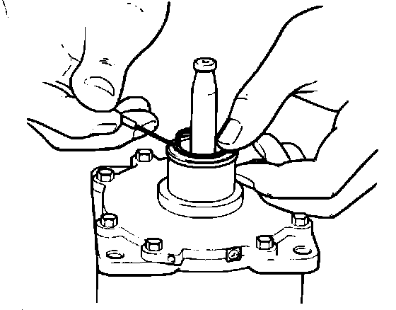
FIGURE 23:
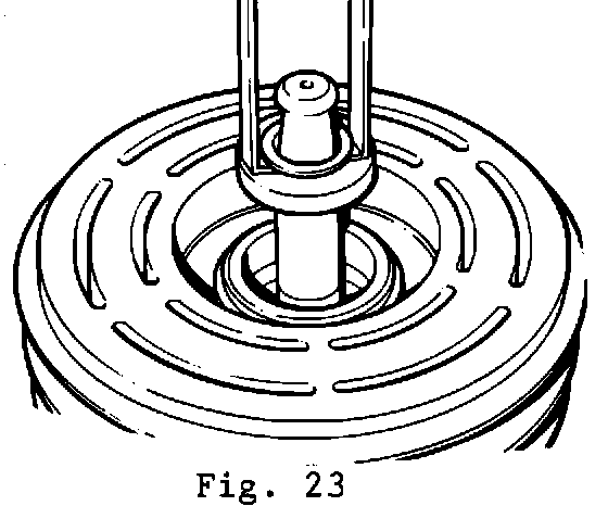
Coat the new O-ring with clean refrigerant oil. Carefully place in the seal groove with the O-ring hook (Fig. 22). Do not scratch the surface. Coat the seal retainer with clean refrigerant oil. Use the tongs and press the retainer lightly against the seal (Fig. 23).
FIGURE 24:
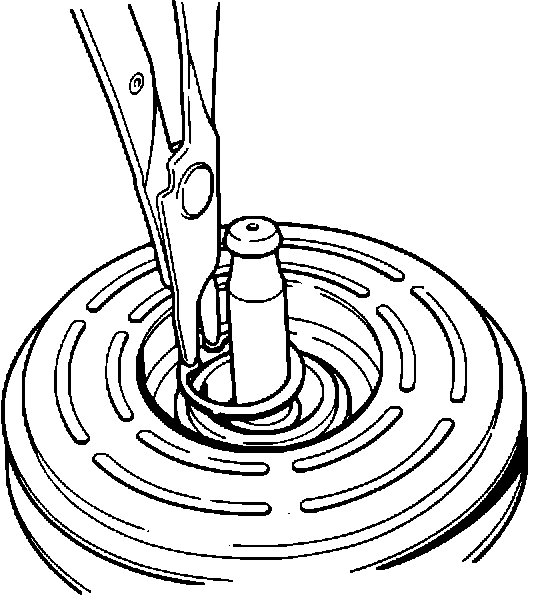
FIGURE 25:
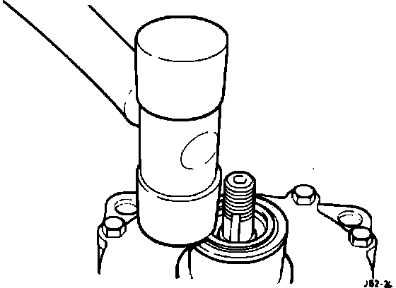
Refit the circlip with the beveled edge outward away from the compressor and the flat side toward the compressor (Fig. 24). It may be necessary to lightly tap the circlip to securely position it in its groove. Refit the clutch spacer shims. Tap a new felt ring into place (Fig. 25). Refit front clutch plate.