Service Procedure
Repair the Vehicle Body Harness for the Front Seat Belt Pre-Tensioner as follows:NOTE:
Use suitable covers to protect upholstery carpet paint etc. when performing this procedure.
Preliminary Steps:
1. Write down all radio station presets.
2. Remove any accessory (phone charger etc.) from the 12V Power Outlet(s).
WARNING:
^ Do NOT use a "Computer Memory Saver" (9-volt power source) that plugs into the 12V Power Outlet(s) to retain memory settings on the computer and radio.
^ No voltage should be present in the system when performing this procedure.
3. Disconnect both battery cables.
4. Wait at least 3 minutes before proceeding with the following steps.
Remove "B" Pillar Lower Trim Panel
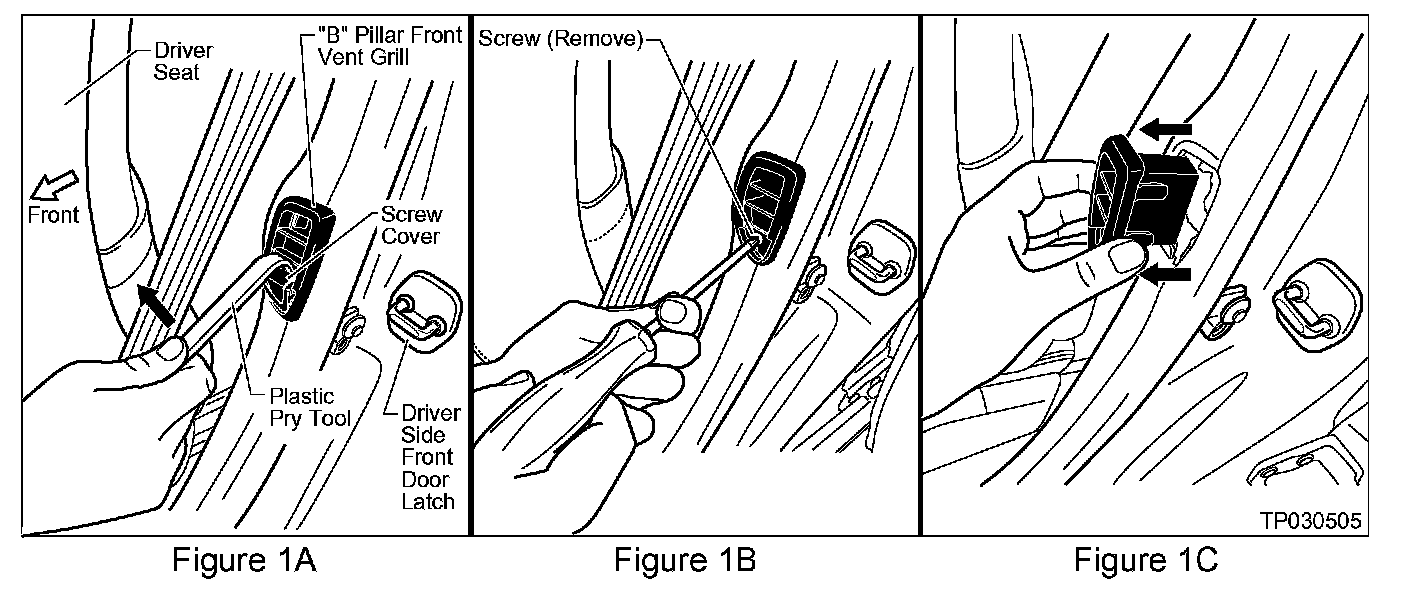
5. Remove the B Pillar Front Vent Grill as follows:
A. Use a Plastic Pry Tool (from essential tool set # J46534) to remove the Screw Cover (see Figure 1A).
B. Remove the Screw from the Vent Grill (see Figure 1B).
C. Carefully pull the Vent Grill out of the B Pillar Lower Trim Panel (see Figure 1C).
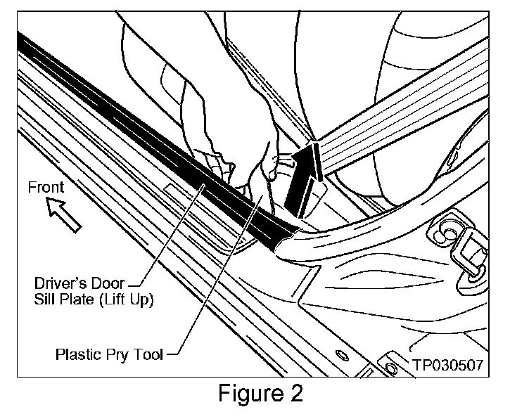
6. Use a Plastic Pry Tool (from essential tool set # J-46534) to release the rear end of the Driver's Door Sill Plate (see Figure 2).
^ This will allow clearance for removing the Door Molding (next step).
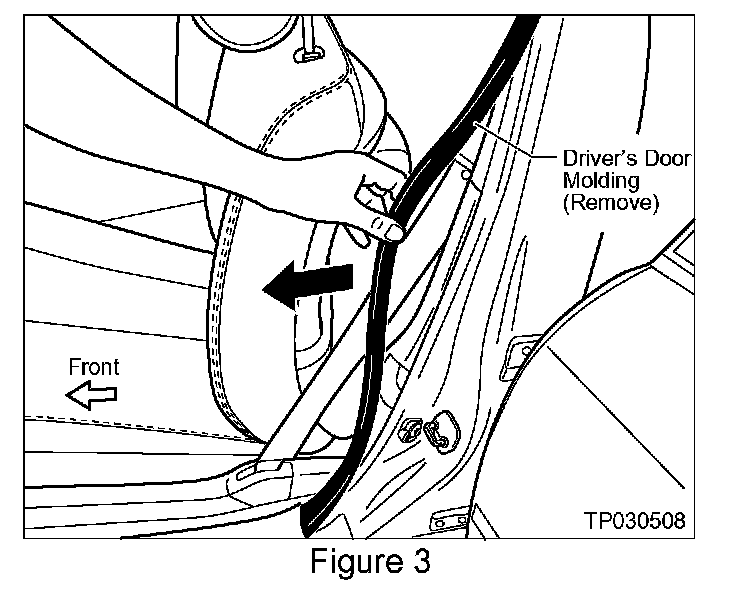
7. Pull the Driver Door Molding UP past the top of the B Pillar Lower Trim Panel (see Figure 3).
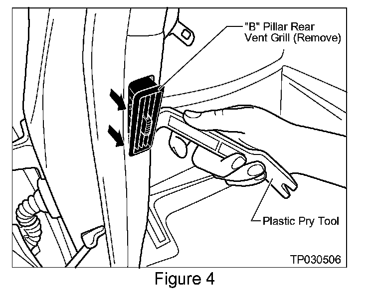
8. Use a Plastic Pry Tool (from essential tool set # J-46534) to remove the B Pillar Rear Vent Grill (see Figure 4).
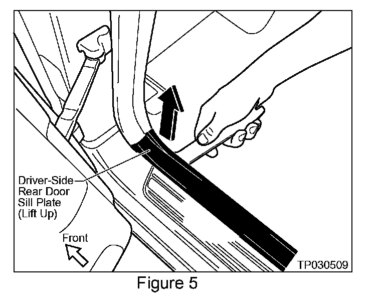
9. Use a Plastic Pry Tool (from essential tool set # J-46534) to release the front end of the Driver-side Rear Door Sill Plate (see Figure 5).
^ This will allow clearance for removing the Door Molding (next step).
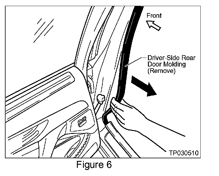
10. Pull the Driver-side Rear Door Molding UP past the top of the B Pillar Lower Trim Panel (see Figure 6).
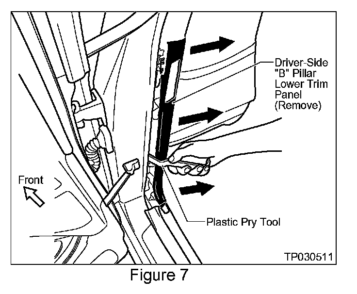
11. Use a Plastic Pry Tool (from essential tool set # J-46534) to remove the Driver-side B Pillar Lower Trim Panel (see Figure 7).
Repair Vehicle Body Harness for Front Seat Belt Pre-Tensioner:
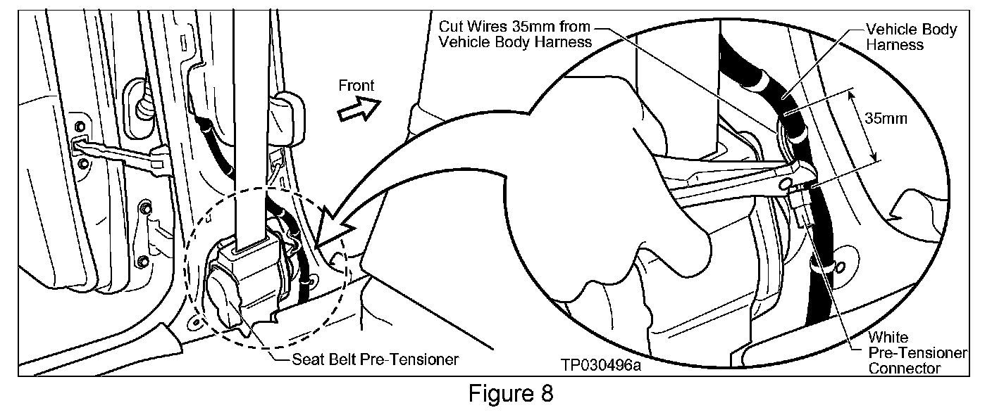
12. Cut the two wires that lead into the White Pre-Tensioner Connector 35 mm (about 1-3/8 inches) from the Vehicle Body Harness (see Figure 8).
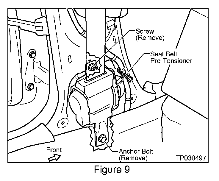
13. Remove one screw and one Anchor Bolt and remove the Seat Belt Pre-Tensioner from the B Pillar (see Figure 9).
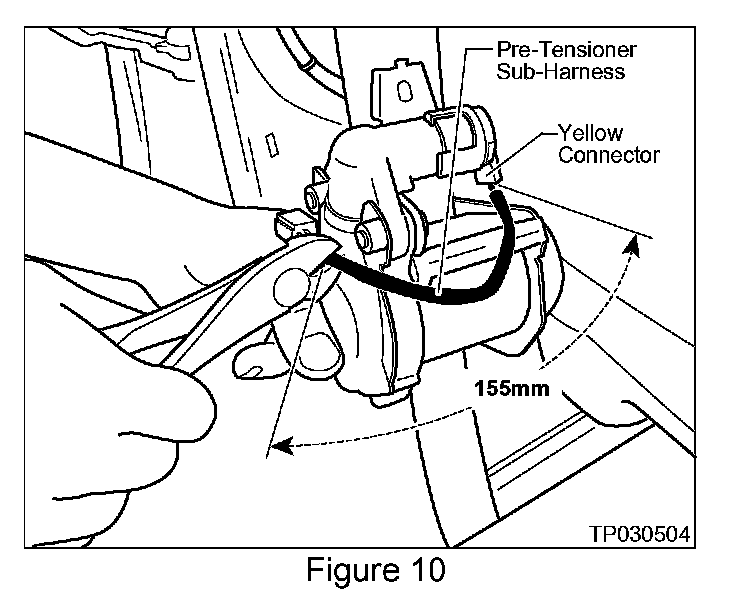
14. Cut the Pre-Tensioner Sub-Harness 155 mm (about 5-7/8 inches) from the Yellow Connector (see Figure 10).
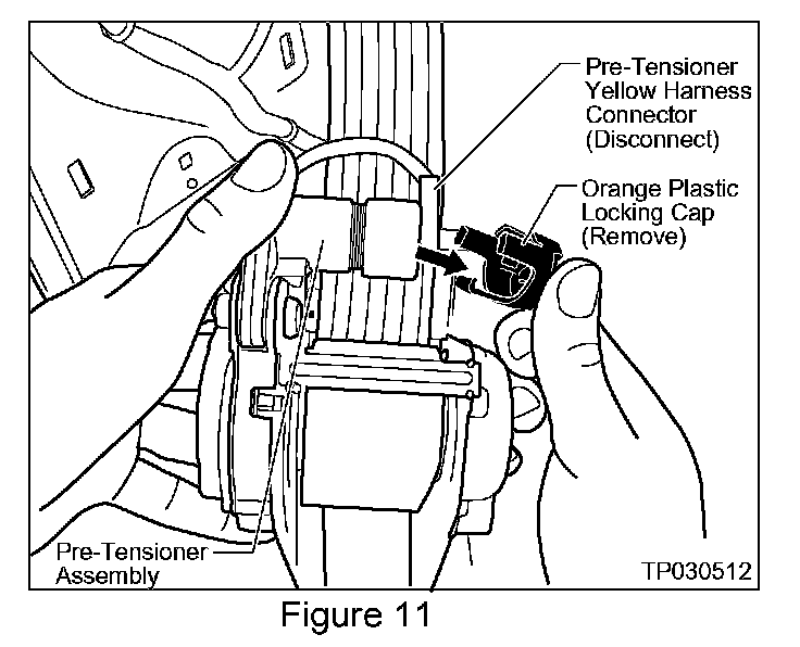
15. Remove the Orange Plastic Locking Cap from the Pre-Tensioner. Then disconnect the Yellow Connector from the Pre-Tensioner (see Figure 11).
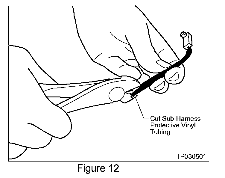
16. Cut the Pre-Tensioner Sub-Harness Protective Vinyl Tubing 50 mm (about 2 inches) to access the wires (see Figure 12).
^ Don't cut the wires themselves or the wire insulation.
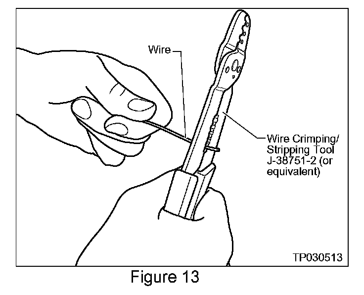
17. Use essential Crimper tool # J-38751-2 to strip off (see Figure 13) about 10 mm of insulation from the ends of:
^ The two Pre-Tensioner Sub-Harness Wires
^ The two wires coming out of the Body Harness (the ones you cut earlier)
NOTE:
Use the correct size opening in the wire Crimper tool so you won't cut off any strands of wire. Less strands reduces the ability of the wire to handle the expected electrical load.
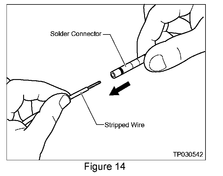
18. Slide a Solder Connector over each Pre-Tensioner Sub-Harness wire (see Figure 14) then:
^ Twist one of the Sub-Harness wires onto one of the Body Harness wires (it does not matter which wire).
^ Twist the other Sub-Harness wire onto the remaining Body Harness wire.
NOTE:
^ Matching the wire colors between the Sub-Harness and Body Harness (polarity) is not critical.
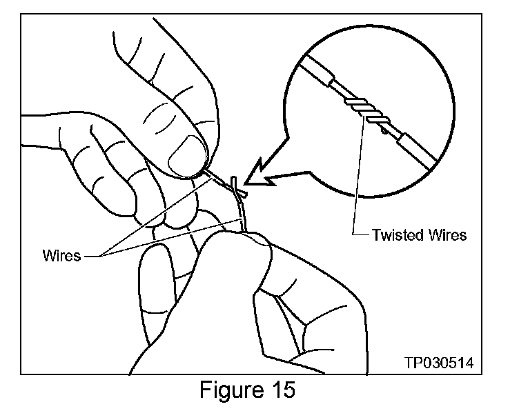
^ Make sure the wires are securely twisted together (see Figure 15).
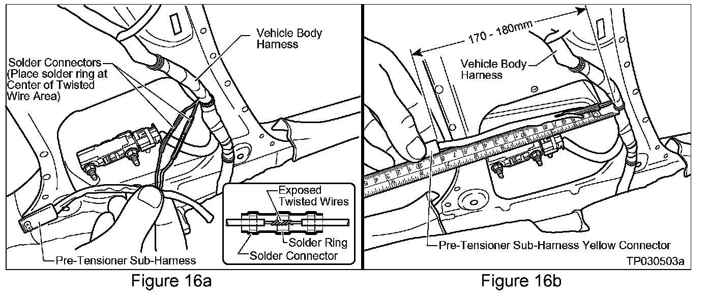
19. Position the Solder Connectors so that the solder ring (in the connector see Figure 16a) is centered around the exposed twisted wire area (see Figure 16a).
20. Measure the length of the Pre-Tensioner Sub-Harness between the Yellow Connector and the Body Harness (see Figure 16b). The length should be within 170-180 mm (about 6-5/8 to 7-1/8 inches).
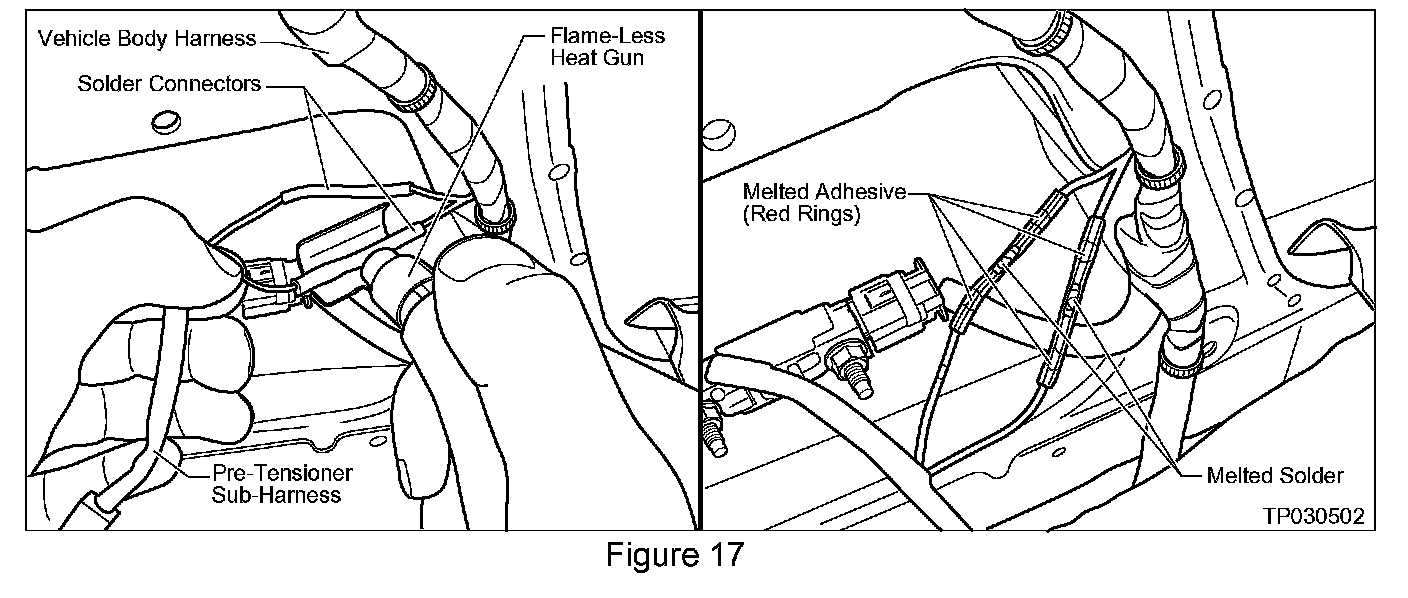
21. Use the special Flame-Less Heat Gun # J-46538 (essential tool) to heat the Solder Connector. This operation will:
^ Melt the solder (silver ring inside solder connector) into the exposed twisted wire area (see Figure 17)
^ Melt the sealant (red rings inside solder connector) onto the wires (see Figure 17)
^ Shrink the plastic sleeve onto the wires
WARNING:
The Flame-Less Heat Gun and the Solder Connectors become HOT during the soldering process. Allow the Gun and connectors to cool down before handling them.
Important Soldering Tips:
^ Position the Solder Connector in the middle of the heat shield (of the Heat Gun).
^ Start heating the connector from the center and move back and forth (side to side) and around to allow even distribution of the heat to the entire connector.
^ Make sure the solder completely flows into the exposed twisted wires and the adhesive properly seals the wire insulation to the connector sleeve. Stop applying the heat immediately after this happens.
CAUTION:
Be careful not to damage the connector or wires with the heat gun:
^ Do NOT apply heat for more than about 40 seconds.
^ Do NOT overheat the connector or wires (i.e. severe darkening of connector sleeve or wire insulation).
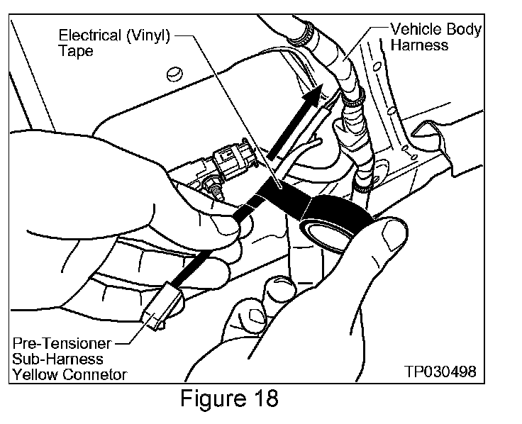
22. Slide the protective vinyl tubing (on the PreTensioner Sub-Harness) all the way against the Yellow Connector. Then wrap the Sub-Harness/Solder Connectors with Electrical (Vinyl) Tape (see Figure 18).
Re-Assembly
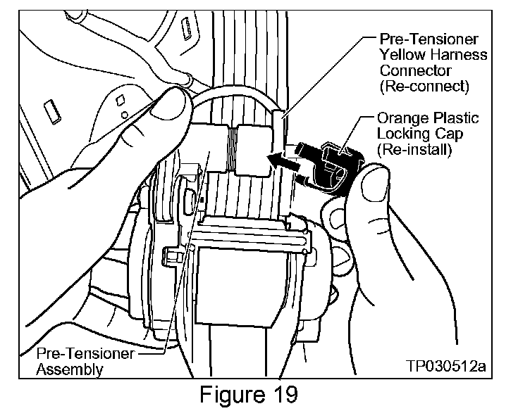
23. Securely re-connect the Pre-Tensioner Sub-Harness Yellow Connector to the Pre-Tensioner. Then re-install the Orange Plastic Locking Cap (see Figure 19).
24. Re-install the Pre-Tensioner to the B Pillar:
Tighten the Anchor Bolt to: 43.1 - 54.9 N-m (4.4 - 5.5 Kg.m, 32 - 40 ft.lb)
IMPORTANT:
Make sure the wire harnesses are correctly routed and NOT rubbed chatted or pinched by surrounding components.
25. Re-install the B Pillar Lower Trim Panel and related components in the reverse order they were removed.
Check Air Bag Module Warning Light (on Instrument Panel):
CAUTION:
Make sure the ignition key is in the OFF position and all doors are closed before reconnecting the battery cables (next step).
26. Re-connect both battery cables.
27. From the passenger side turn the ignition key to the ON position.
a. If the Air Bag Module Warning Light turns OFF after 7 seconds proceed to "Final Steps".
b. If the Air Bag Module Warning Light does NOT turn ON at first does NOT turn OFF or blinks refer to the applicable Service Manual for diagnosis/repair. Then proceed to "Final Steps".
Final Steps:
28. Re-program all radio station presets.
29. Re-set the clock.