Assembly
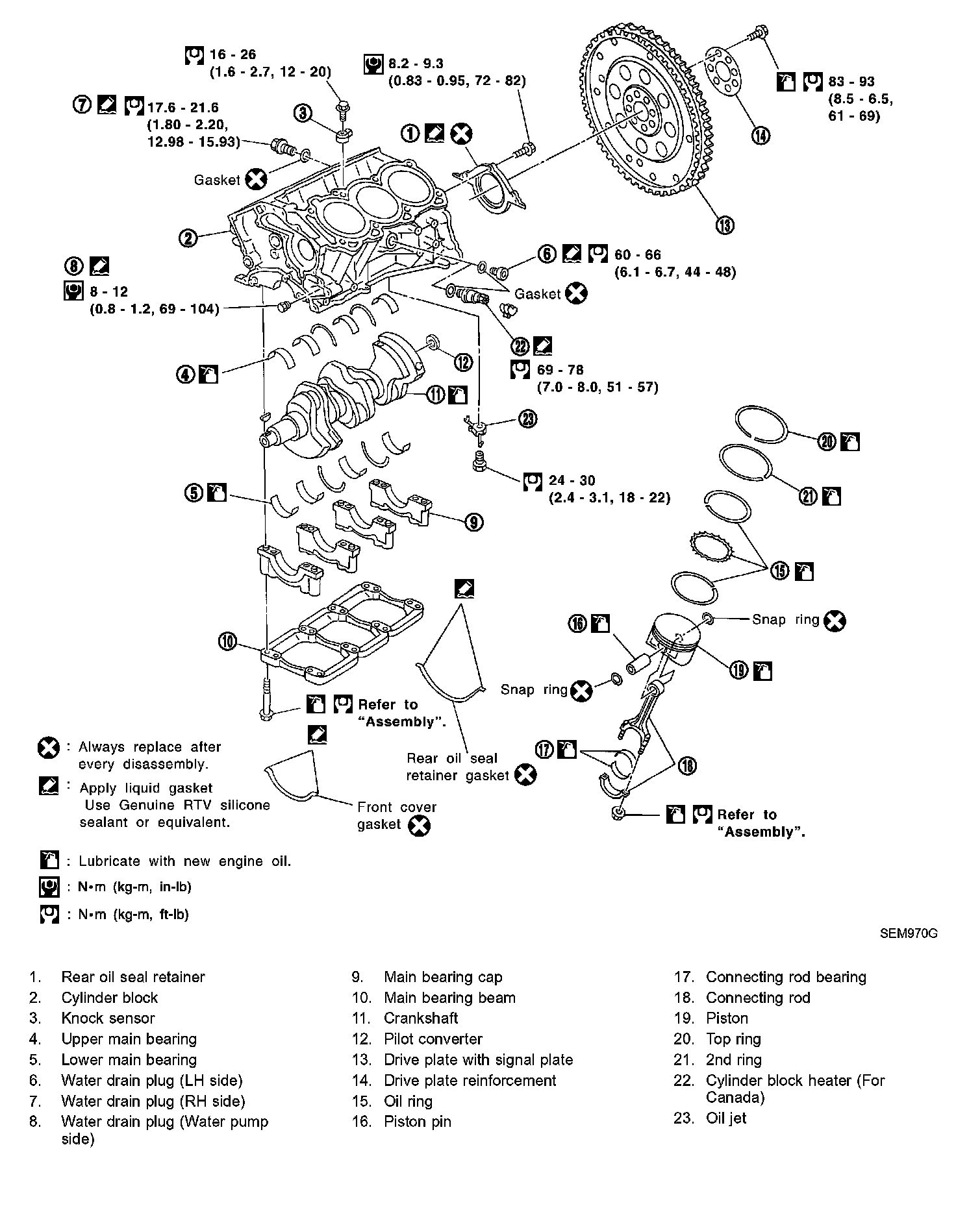
Components
PISTON
1. Install new snap ring on one side of piston pin hole.
2. Heat piston to 60 to 70°C (140 to 158°F) and assemble piston, piston pin, connecting rod and new snap ring.
^ Align the direction of piston and connecting rod.
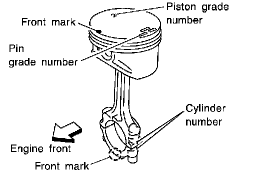
^ Numbers stamped on connecting rod and cap correspond to each cylinder.
^ After assembly, make sure connecting rod swings smoothly.
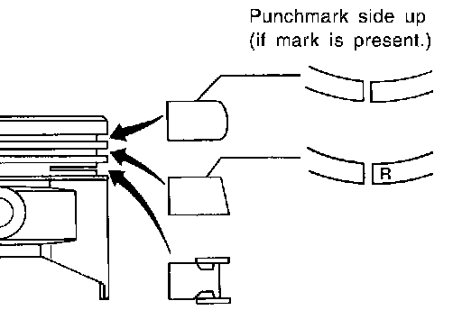
3. Set piston rings as shown.
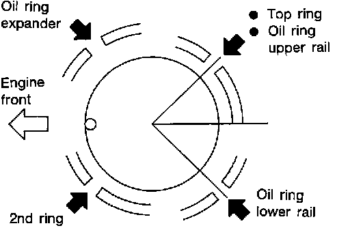
CAUTION:
^ When piston rings are not replaced, make sure that piston rings are mounted in their original positions.
^ When replacing piston rings, those without punchmarks present can be mounted with either side up.
^ Align piston rings so that end gaps are positioned as shown in the figure.
OIL JET
1. Install oil jets.
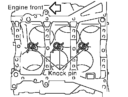
^ Insert oil jet knock pin into the cylinder block knock pin hole, and tighten the mounting bolts.
CRANKSHAFT
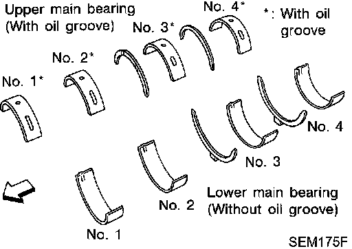
1. Set main bearings in their proper positions on cylinder block and main bearing beam.
^ Confirm that correct main bearings are used.
2. Instructions for re-use of main bearing cap bolts.
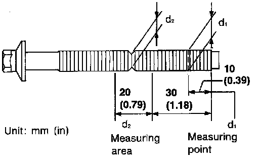
^ A plastic zone tightening method is used for tightening main bearing cap bolts. Measure d1 and d2 as shown in the figure.
d2: Select minimum diameter in the measuring area. If the difference between d1 and d2 exceeds the limit, replace the bolts with new ones.
Limit (d1 - d2): 0.11 mm (0.0043 inch)
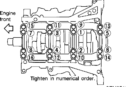
3. After installing crankshaft, main bearing cap, main bearing beam and bearing cap bolts, tighten bearing cap bolts in numerical order as shown.
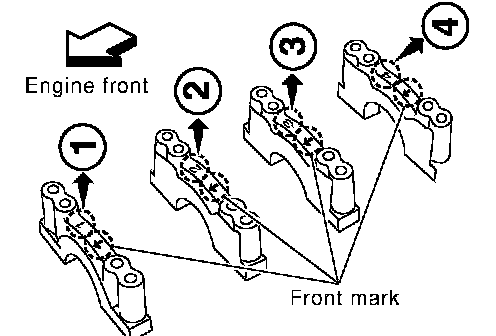
^ Make sure that the front mark on the main bearing beam faces the front of the engine.
^ Tightening procedure
a. Tighten all bolts to 32 to 38 Nm (3.3 to 3.9 kg-m, 24 to 28 ft. lbs.) in several different steps.
b. Turn all bolts 90 to 95 degrees clockwise with angle wrench.
^ Prior to tightening bearing cap bolts, place bearing beam in its proper position by shifting crankshaft in the axial direction.
^ After securing bearing cap bolts, make sure crankshaft turns smoothly by hand.
^ Lubricate threads and seat surfaces of the bolts with new engine oil.
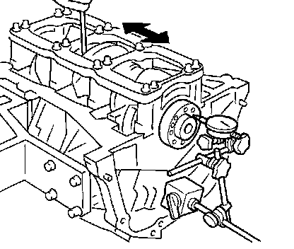
4. Measure crankshaft end play.
Crankshaft end play:
Standard 0.10 - 0.25 mm (0.0039 - 0.0098 inch)
Limit 0.30 mm (0.0118 inch)
If the measured value exceeds the limit, replace the thrust bearings and measure again.
If it still exceeds the limit, replace the crankshaft also.
5. Install connecting rod bearings in connecting rods and connecting rod caps.
^ Confirm that correct bearings are used.
a. When installing the connecting rod bearings, apply engine oil to the bearing surface (inside). Do not apply oil to the back surface, but thoroughly clean it.
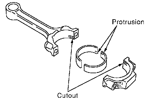
b. When installing, align the connecting rod bearing stopper protrusion with the cutout of the connecting rod to install.
c. Check the oil hole on the connecting rod and that on the corresponding bearing are aligned.
6. Install pistons with connecting rods.
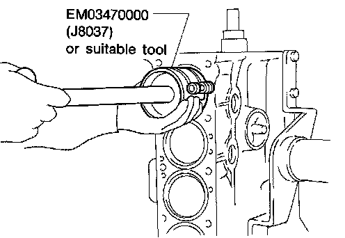
a. Install them into corresponding cylinders with Tool.
^ Be careful not to scratch cylinder wall with the connecting rod.
^ Arrange so that front mark on piston head faces toward engine front.
b. Install connecting rod caps.
^ Lubricate threads and seat surfaces with new engine oil.
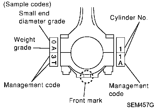
^ Install so that the cylinder number stamped on the connecting rod agrees with that stamped on cap side.
^ Make sure that front mark on the connecting rod cap faces the front of the engine.
c. Re-use connecting rod cap bolts as follows.
^ Make sure that the bolts can be smoothly screwed-in to the end manually.
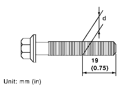
^ If not, measure the outer diameter "d" shown in the figure.
Outer diameter "d" of connecting rod cap bolt:
Standard 7.90 - 8.00 mm (0.3110 - 0.3150 inch)
Limit 7.75 mm (0.3051 inch)
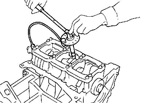
d. Tighten connecting rod cap bolts to the specified torque.
Connecting rod cap bolt:
(1) Tighten nuts to 19 to 21 Nm (1.9 to 2.1 kg-m, 14 to 15 ft. lbs.).
(2) Turn nuts 90 to 95 degrees clockwise with angle wrench.
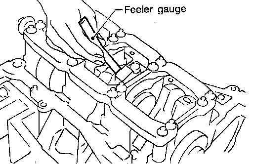
7. Measure connecting rod side clearance.
Connecting rod side clearance:
Standard 0.20 - 0.35 mm (0.0079 - 0.0138 inch)
Limit 0.40 mm (0.0157 inch)
If the measured valve exceeds the limit, replace the connecting rod and measure again. If it still exceeds the limit, replace the crankshaft also.
8. Install rear oil seal retainer.
KNOCK SENSOR
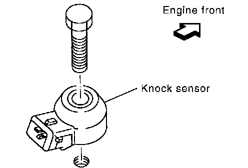
1. Install knock sensor.
^ Make sure that there is no foreign material on the cylinder block mating surface and the back surface of the knock sensor.
^ Install knock sensor so that connector faces rear of engine.
^ Do not tighten the mounting bolts while holding the connector.
^ Make sure that the knock sensor does not interfere with other parts.
CAUTION: If any impact by dropping is applied to the knock sensor, replace it with new one.
^ After installing knock sensor, connect sub-harness, and lay it out to rear of engine.
REPLACEMENT OF PILOT CONVERTER
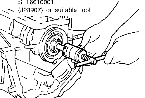
1. Remove pilot converter using tool or suitable tool.
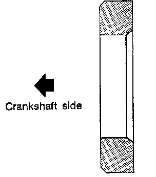
2. Install pilot converter as shown.
DRIVE PLATE
Install drive plate.
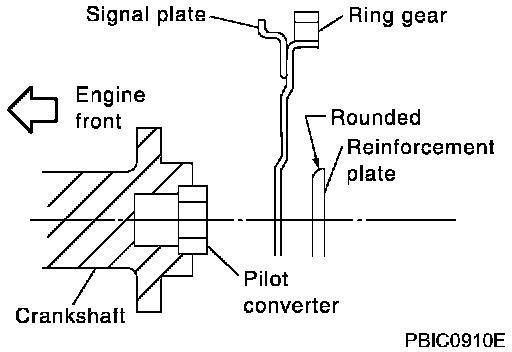
^ Install the drive plate and reinforce plate in the direction shown in the figure.
^ Align dowel pin of crankshaft rear end with pin holes of each parts.
^ Secure the crankshaft using a ring gear stopper.
^ Tighten the installation bolts crosswise over several times.