Repair Procedures
Replacement
1. Drain the power steering fluid.
2. Remove the front wheel & tire.
Tightening torque :
88.3 - 107.9N.m (9.0 - 11.0kgf.m, 65.1 - 79.6lb-ft)
3. Loosen the bolt (A) and then disconnect the universal joint assembly from the pinion of the steering gear box.
Tightening Torques :
17.7 - 24.5N.m (1.8 - 2.5kgf.m, 13.0 - 18.1lb-ft)
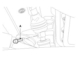
CAUTION:
Keep the neutral-range to prevent the damage of the clock spring inner cable when you handle the steering wheel.
4. Loosen the castle nut.
Tightening torque :
83.4 - 107.9N.m (8.5 - 11.0kgf.m, 61.5 - 79.6lb-ft)
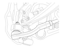
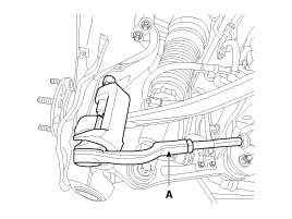
5. Disconnect the tie-rod end (A) from the knuckle using a SST (09568-2J100).
Tightening torque :
78.5 - 88.3N.m (8.0 - 9.0kgf.m, 57.9 - 65.1lb-ft)
6. Loosen the tube bolts and then disconnect the pressure and return tube.
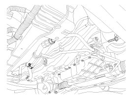
7. Remove the steering gear box bracket (A) by loosening the bolts.
Tightening torque :
19.6 - 29.4N.m (2.0 - 3.0kgf.m, 14.5 - 21.7lb-ft)
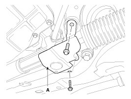
8. Remove the steering gear box (A) by loosening the bolts.
Tightening torque :
83.4 - 107.9N.m (8.5 - 11.0kgf.m, 61.5 - 79.6lb-ft)
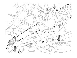
9. Installation is the reverse of the removal.
10. Check the alignment.
Disassembly
1. Loosen the lock nut (A) and then unscrew the tie-rod end (B) and lock nut from the tie-rod.
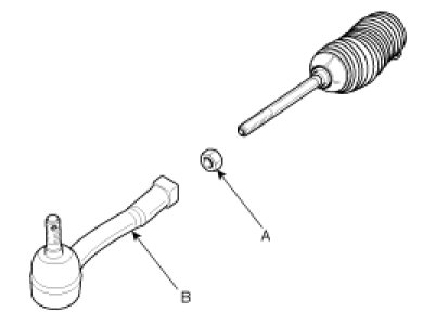
2. Remove the clip (A) and band (B) and then pull the bellows (C) away from the end of the tie-rod.
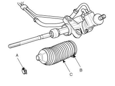
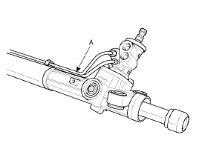
3. Remove the feed tubes (A) from the steering gear box.
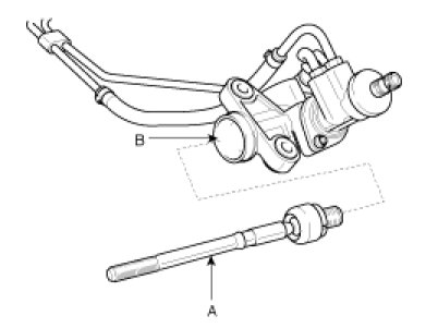
4. Unscrew the tie-rod (A) from the rack bar (B).
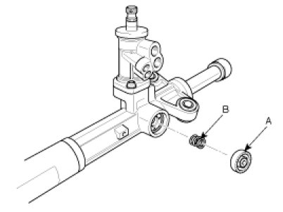
5. Remove the lock nut (A) and yoke plug and then pull out the yoke spring (B) and support yoke assembly.
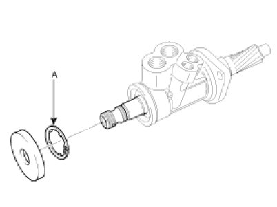
6. Remove the snap ring (A).
7. Remove the oil seal (A), bearing (B) and snap ring (C).
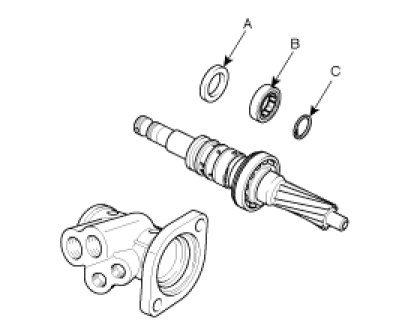
CAUTION:
Do not allow dust, dirt, or foreign materials to contact the disassembled parts or inside of the valve assembly housing.
8. Unscrew the rack bush and pull the rack bar out of the rack housing.
9. Reassembly is the reverse of the disassembly.
Inspection
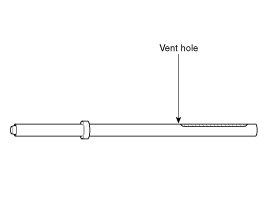
1. Rack
A. Check for rack tooth face damage or wear.
B. Check for oil seal contact surface damage or wear.
C. Check for bending or twisting of rack.
D. Check for oil seal ring damage or wear.
E. Check for oil seal damage or wear.
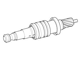
2. Pinion valve
A. Check for pinion gear tooth face damage or wear.
B. Check for oil seal contact surface damage.
C. Check for seal ring damage or wear.
D. Check for oil seal damage or wear.
3. Bearing
A. Check for seizure or abnormal noise during bearing rotation.
B. Check for excessive play.
C. Check for missing needle bearing rollers.
4. Others
A. Check for damage of the gear housing cylinder bore.
B. Check for boot damage, cracking or ageing.