Transmission Reassembly
MANUAL TRANSAXLEREASSEMBLY
1. Assemble the reverse idler gear assembly.
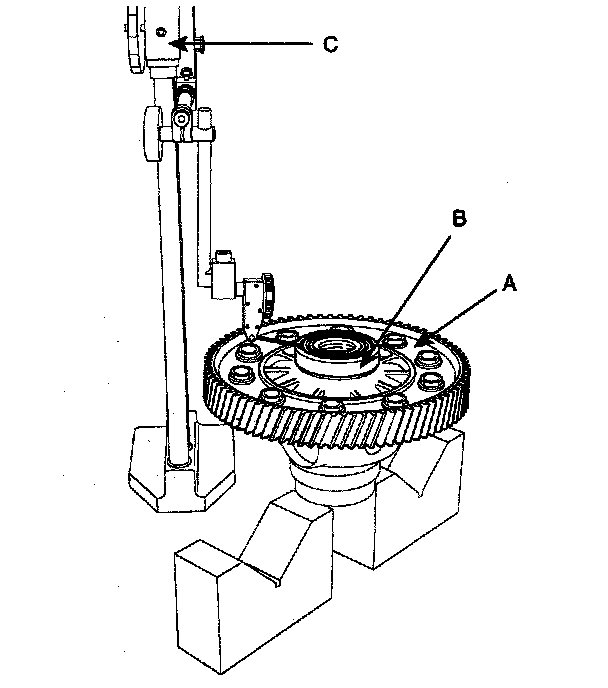
2. Measure the height with a height gauge (C), after fixing the taper roller bearing outer race (B) to the differential assembly (A).
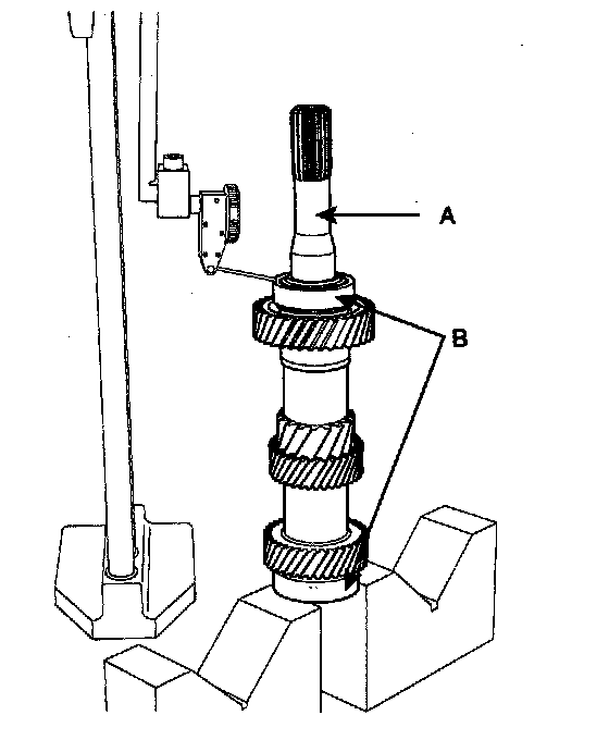
3. After installing the taper roller bearing outer race (B) to both sides of the input shaft (A), measure the height with a gauge.
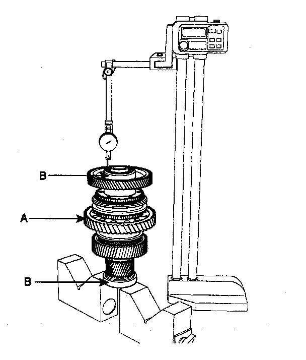
4. After installing the taper roller bearing outer race (B) to both sides of the 1st output shaft (A), measure the height with a gauge.
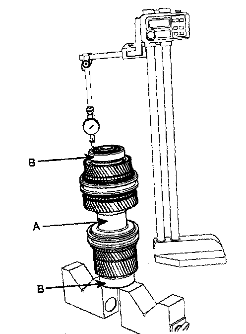
5. After installing the taper roller bearing outer race (B) to both sides of the 2nd output shaft (A), measure the height with a gauge
6. Assemble oil seals and guides to the clutch housing (A).
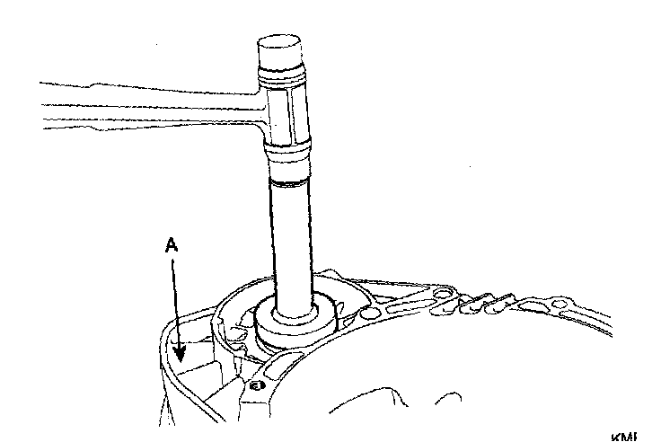
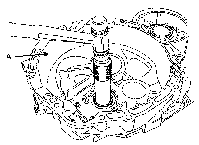
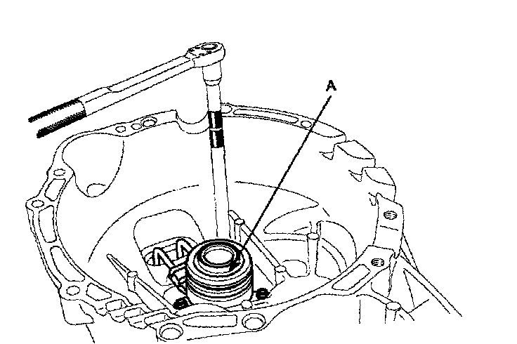
7. Install the concentric slave cylinder assembly (A).
TORQUE: 11.8 - 14.7 Nm (120 - 150 kgf-cm, 8.7 - 10.8 ft. lbs.) Give it a series of tightenings
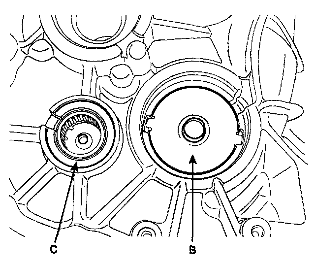
8. Fix the oil guides (B), bearing outer races, dowel pins and spacers (C) to the clutch housing (A).
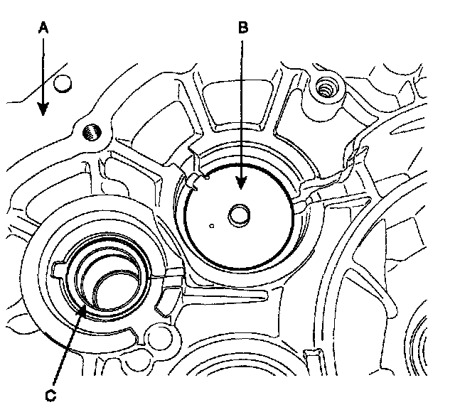
9. Insert a rubber bushing in the hole for the concentric slave cylinder.
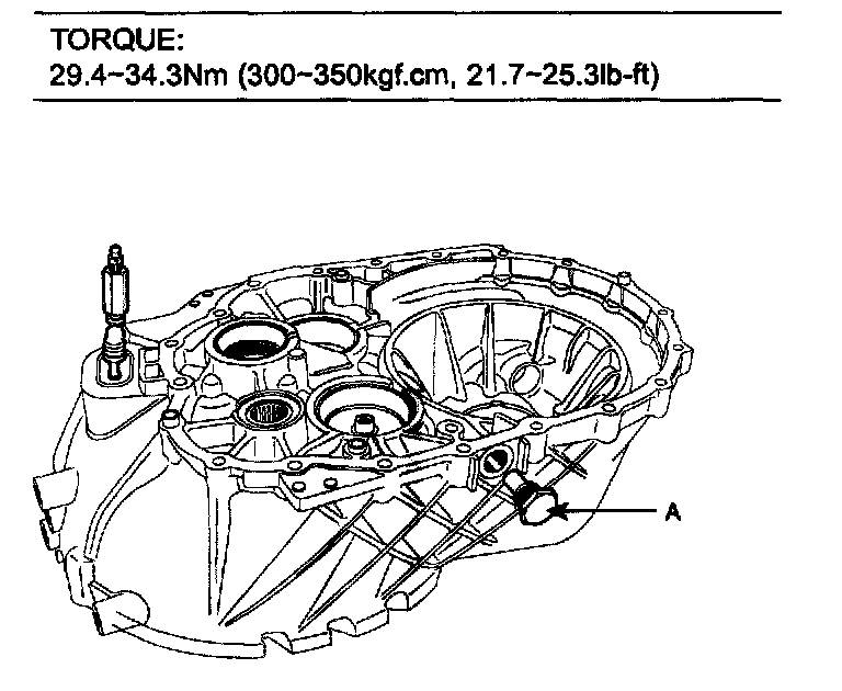
10. Tighten the magnetic plug (A).
TORQUE: 29.4 - 34.3 Nm (300 - 350 kgf-cm, 21.7 - 25.3 ft. lbs.)
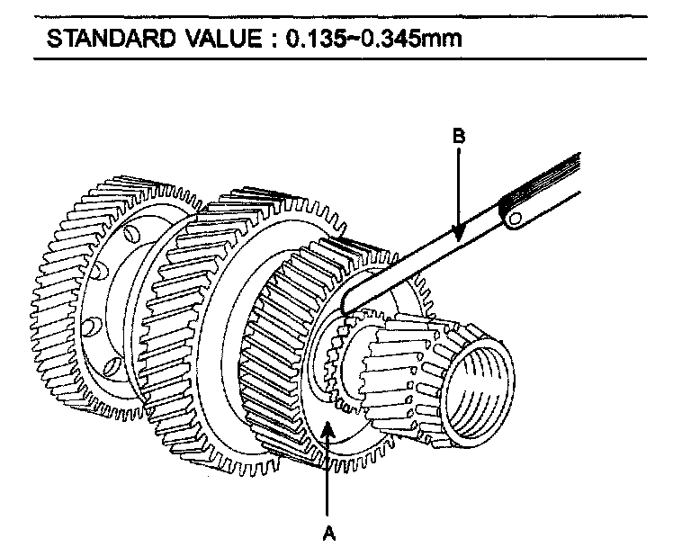
11. Measure the end play with a thickness gauge (B) in the reverse gear (A) of the 1st output shaft.
STANDARD VALUE: 0.135 - 0.345 mm
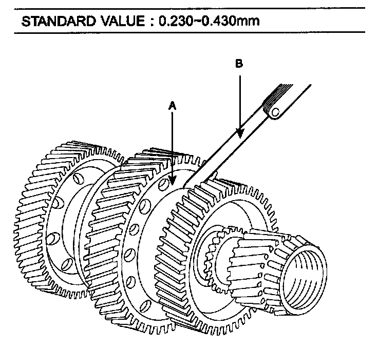
12. Measure the end play with a thickness gauge (B) in the 1st gear (A) of the 1st output shaft.
STANDARD VALUE: 0.230 - 0.430 mm
STANDARD VALUE:
13. Measure the end play with a thickness gauge (B) in the 2nd gear (A) of the 1st output shaft.
STANDARD VALUE: 0.230 - 0.430 mm
STANDARD VALUE:
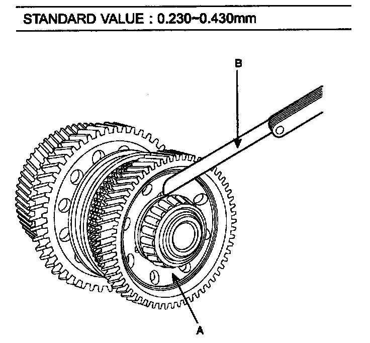
14. Measure the end play with a thickness gauge (B) in the 5th gear of the 2nd output shaft (A).
STANDARD VALUE: 0.125 - 0.305 mm
STANDARD VALUE:
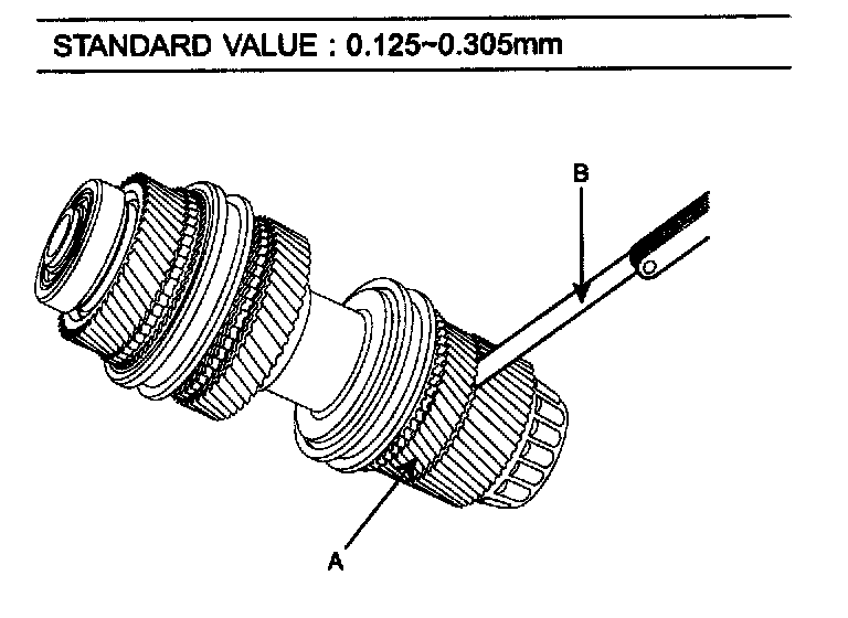
15. Measure the end play with a thickness gauge (B) in the 3rd gear (A) of the 2nd output shaft.
STANDARD VALUE: 0.142 - 0.472 mm
STANDARD VALUE:
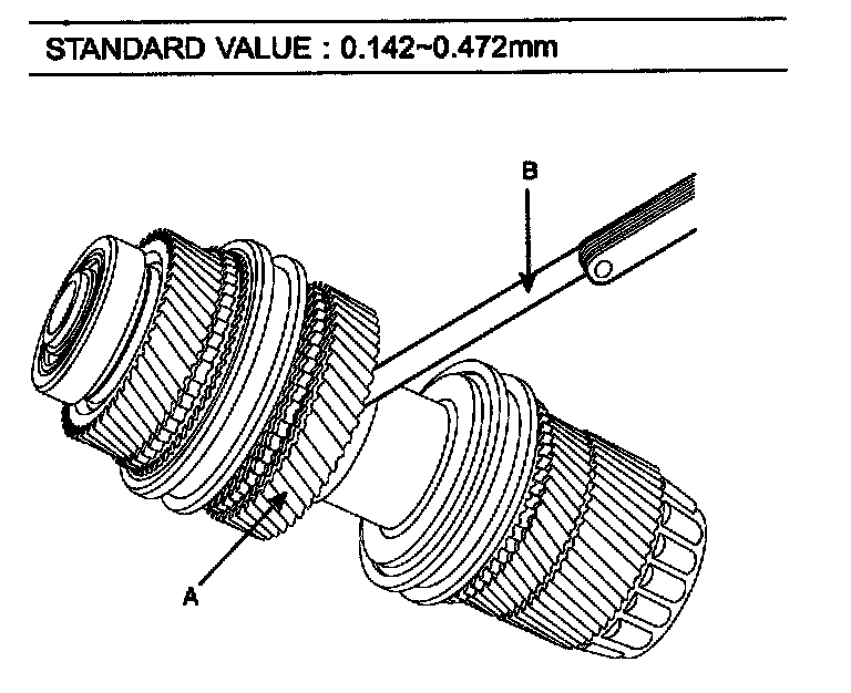
16. Measure the end play with a thickness gauge (B) in the 4th gear (A) of the 2nd output shaft.
STANDARD VALUE: 0.230 - 0.430 mm
STANDARD VALUE:
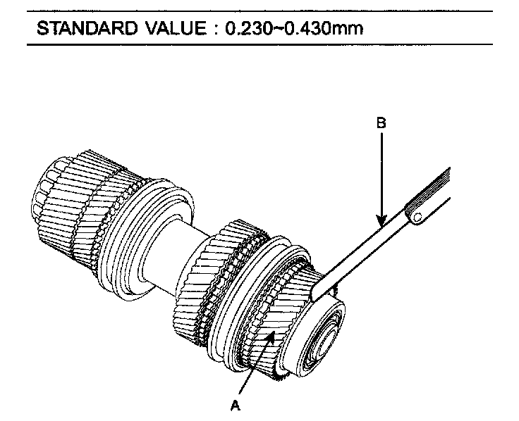
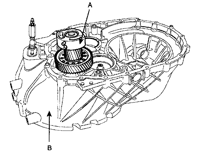
17. Install the reverse idler gear assembly (A) with a spacer in the clutch housing (B).
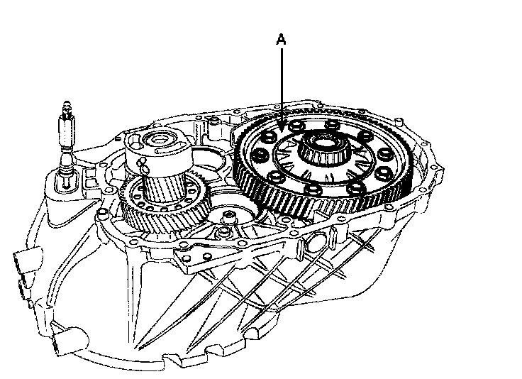
18. Install the differential assembly (A) with a spacer in the clutch housing.
19. Install the 1st output shaft (A) with a spacer in the clutch housing.
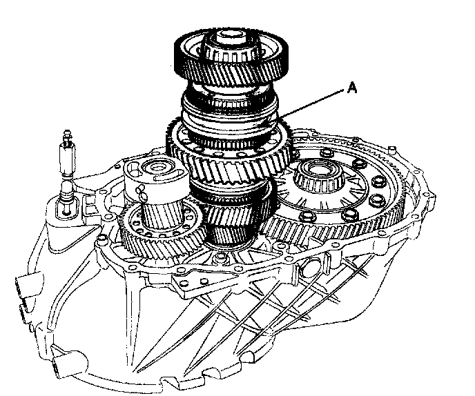
20. Install the input shaft (A) with a spacer in the clutch housing.
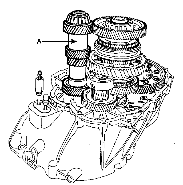
21. Install the 2nd output shaft (A) with a spacer in the clutch housing.
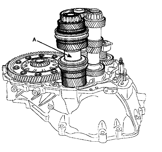
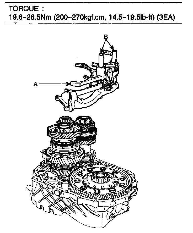
22. Install the shift control shift folk (4EA) (A) and shifts (2EA) (B) and rail support bracket.
TORQUE: 19.6 - 26.5 Nm (200 - 270 kgf-cm, 14.5 - 19.5 ft. lbs.) (3EA)
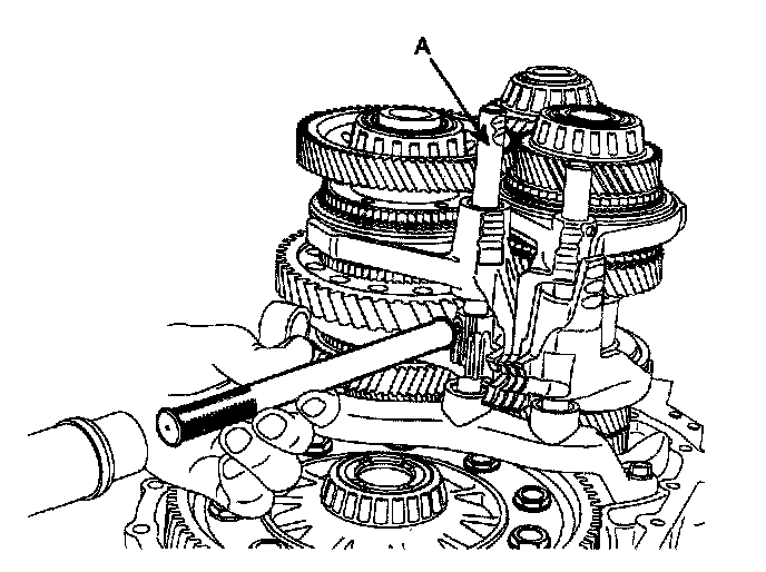
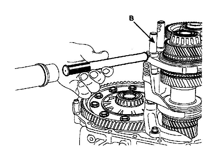
23. Fix them by inserting a pin into the shift rail (A, B).
NOTE: Strike the spring pins with slit facing front or rear side.
24. Insert spacers, bushings and bearing outer races in the transaxle case.
NOTE:
Differential end play [mm (inch)]. 0.15T - 0.20T (0.0059T - 0.0079T)
Input shaft end play [mm (inch)]. 0.05T -0 (0.0020T-0)
1st output shaft end play [mm (inch)]. 0.05T - 0.10T (0.0020T-0.0039T)
2nd output shaft end play [mm (inch)]. 0.05T-0.10T (0-0020T-0.0039T)
Spacer thickness [mm (inch)] = Clutch housing height [mm (inch)] + Transaxle case [mm (inch)] Measured length [mm (inch)]. + end play + tolerance value 0.05 mm (0.0020 inch)
When measuring the length of the output shaft, the outer races on both sides should be installed to the output shaft. Measure the length at least 3 other points and take the average value for accuracy. When measuring end play, take the average. Tolerance means the applied value of shafts and differential length for the transaxle case weight.
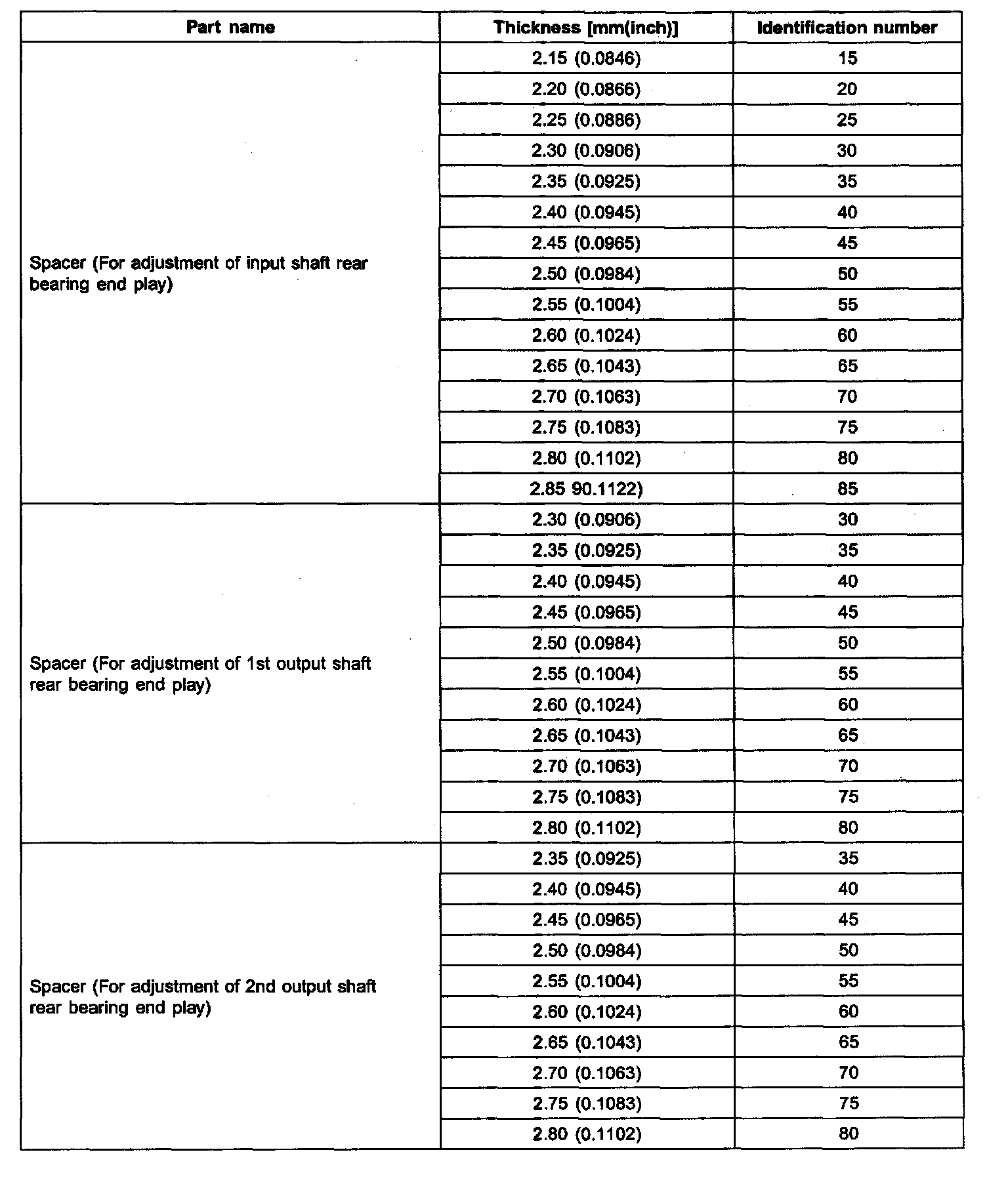
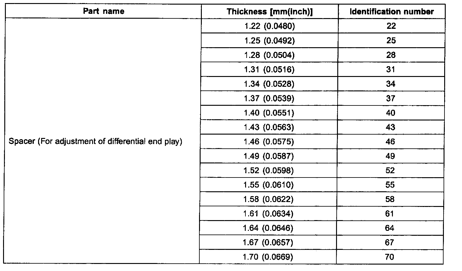
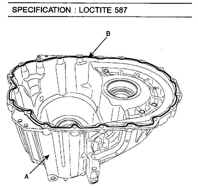
25. Apply the liquid gasket (B) on the transaxle case (A).
SPECIFICATION: LOCTITE 587
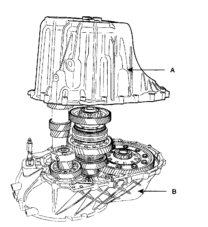
26. Align the pin position with the hole on the reverse idler gear damper.
27. Install the transaxle case (A) with the clutch housing (B).
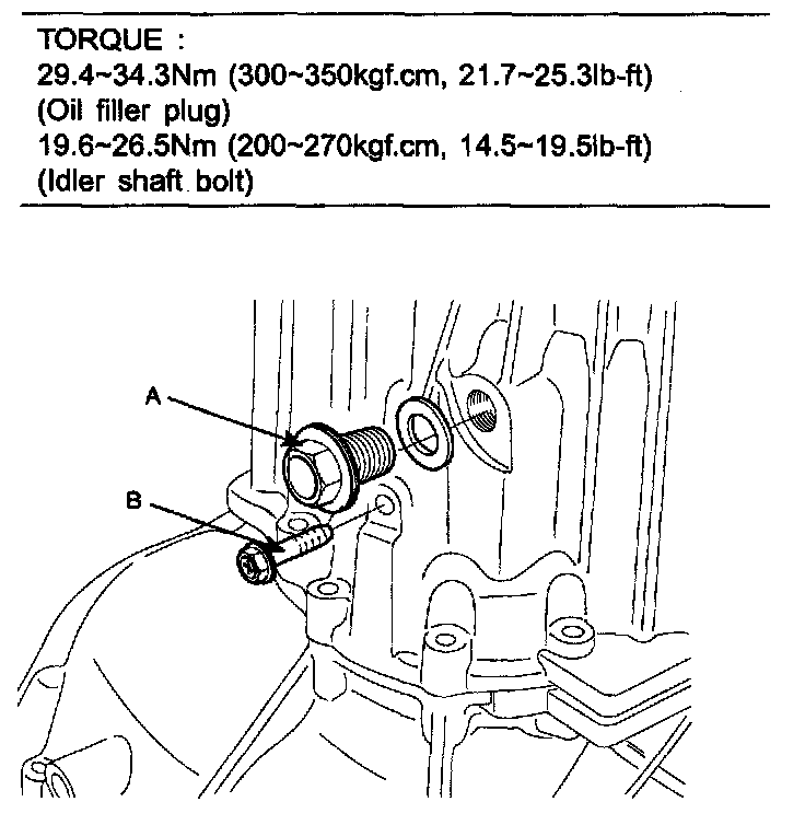
28. Tighten the oil filler plug (A) and idler shaft bolt (B).
TORQUE: 29.4 - 34.3 Nm (300 - 350 kgf-cm, 21.7 - 25.3 ft. lbs.)
(Oil filler plug) 19.6 - 26.5 Nm (200 - 270 kgf-cm, 14.5 - 19.5 ft. lbs.) (Idler shaft bolt)
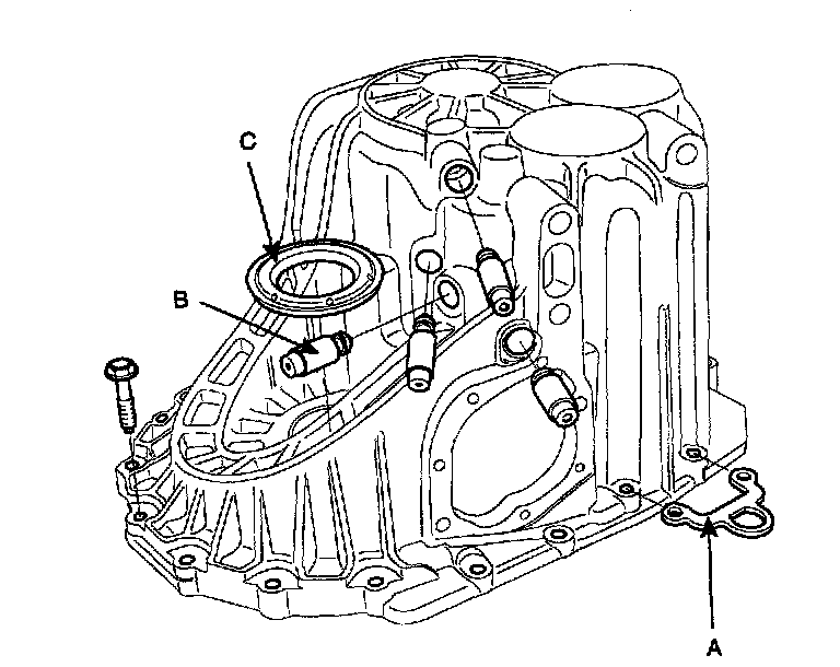
29. Fix the transaxle hanger (A), detent pins (4EA) (B) and oil seal (C).
NOTE: Press the detent pins for the step to be the same level as the surface on the transmission case (4 places).
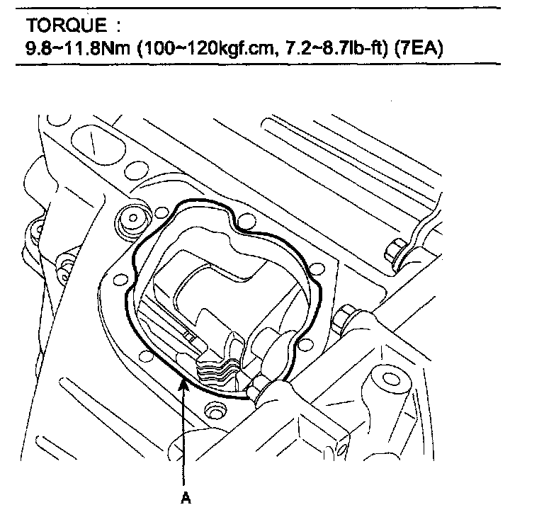
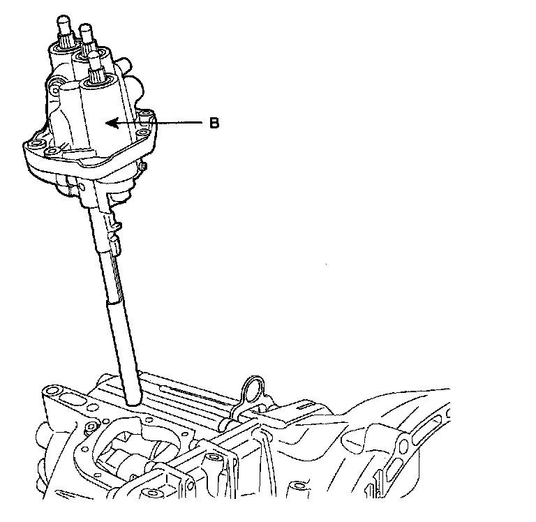
30. Applying a liquid gasket (A) on the contacting surface of the control shaft complete (B), install it.
TORQUE: 9.8 - 11.8 Nm (100 - 120 kgf-cm, 7.2 - 8.7 ft. lbs.) (7EA)
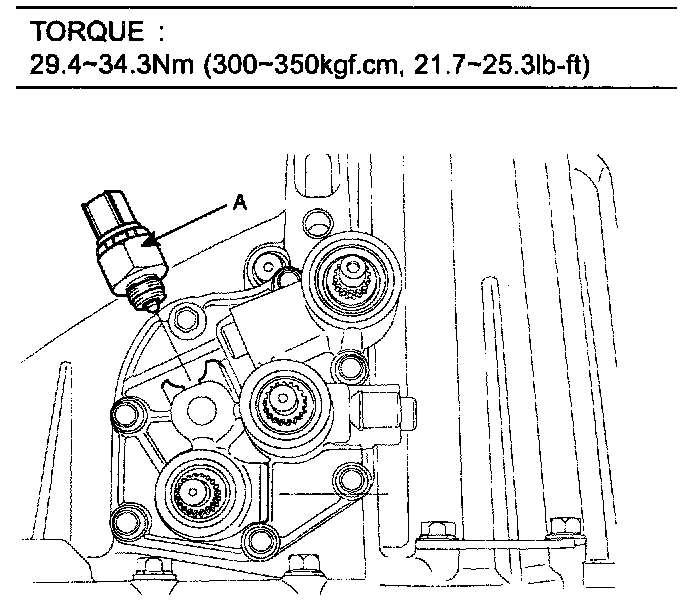
31. Tighten the back up lamp switch (A).
TORQUE: 29.4 - 34.3 Nm (300 - 350 kgf-cm, 21.7 - 25.3 ft. lbs.)
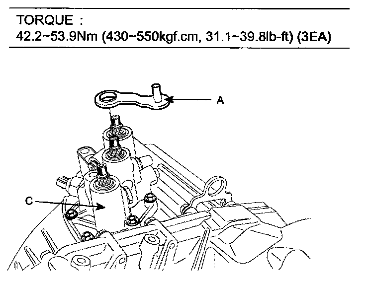
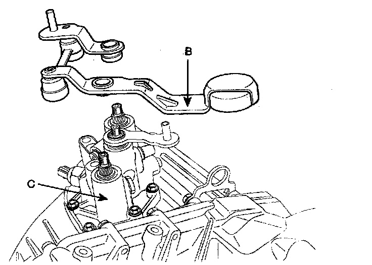
32. Install the select lever (A) and the shift link assembly (B) aligning their position with the identification mark (yellow) which is on the control shaft complete (C).
TORQUE: 42.2 - 53.9 Nm (430 - 550 kgf-cm, 31.1 - 39.8 ft. lbs.) (3EA)
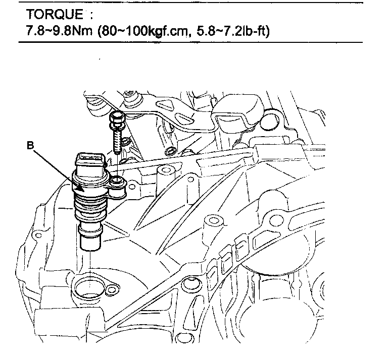
33. Tighten the vehicle speed sensor (B).
TORQUE: 7.8 - 9.8 Nm (80 - 100 kgf-cm, 5.8 - 7.2 ft. lbs.)
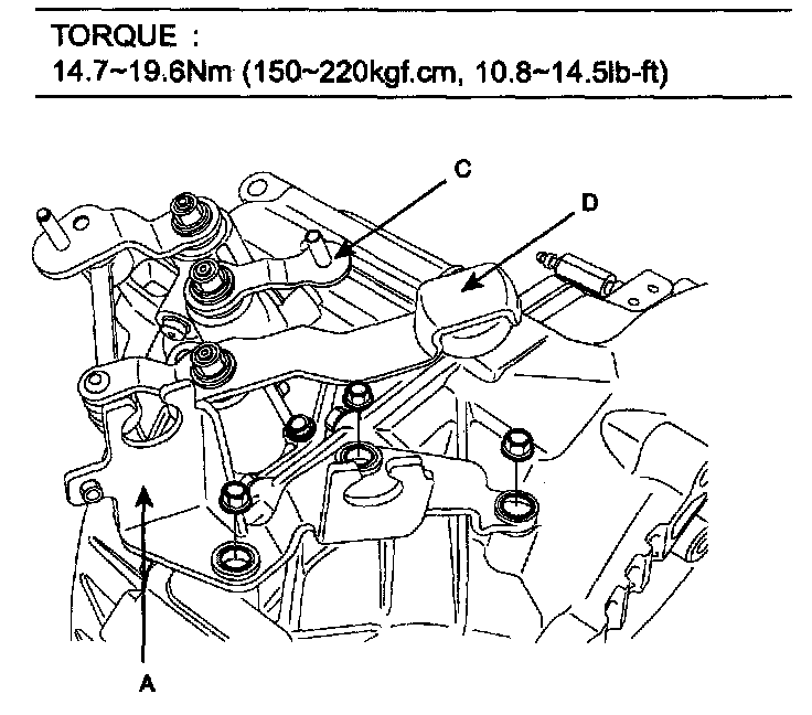
34. Install the shift control cable bracket assembly (A).
TORQUE: 14.7 - 19.6 Nm (150 - 220 kgf-cm, 10.8 - 14.5 ft. lbs.)