Timing Cover: Service and Repair
RemovalFig. 16 Exploded View Of Front Case, Oil Pump & Counter Balance Shaft Assemblies:
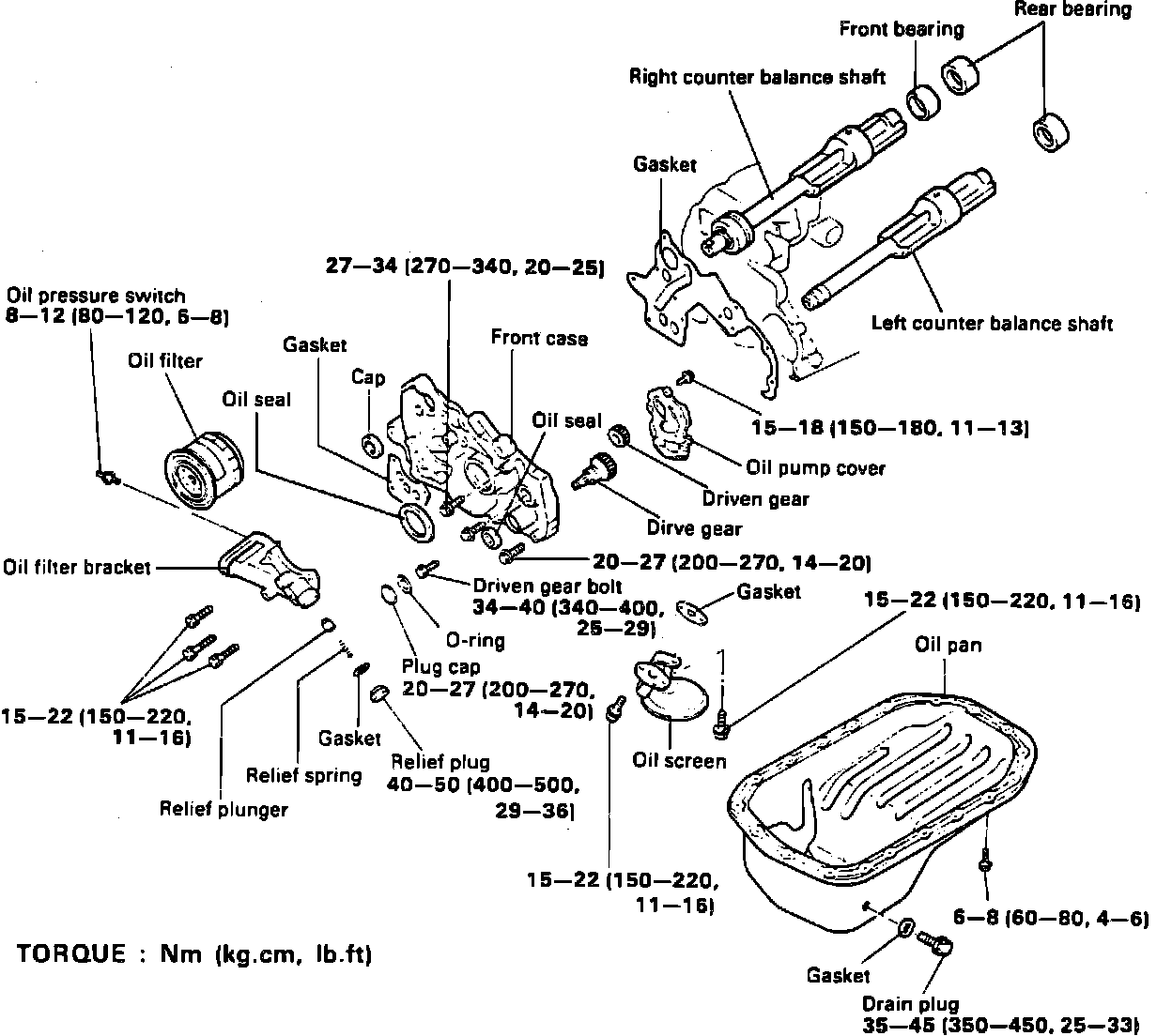
1. Remove timing belt as described under TIMING BELT.
2. Remove oil pan and oil screen, then the relief plunger, spring and valve from oil filter bracket, Fig. 16.
3. Remove oil pressure switch, then the oil filter bracket.
4. Using plug cap wrench 09213-33000 or equivalent, remove plug cap from oil pump portion of front case.
5. Remove lefthand cylinder block plug and insert a screwdriver with a .32 inch diameter shaft into plug hole to secure left counter balance shaft. Screwdriver shaft must be inserted more than 2.4 inches.
6. Remove oil pump driven gear and left counter balance shaft retaining bolt, front case assembly, then the two counter balance shafts from cylinder block.
7. Remove oil pump cover, then the oil pump gears from front case.
8. Remove balance shafts from cylinder block.
9. If necessary, remove counter balance shafts bearings as follows:
a. Remove right counter balance shaft front bearing from cylinder block using counter balance shaft bearing puller 09212-32000 or equivalent.
b. Remove right counter balance shaft rear bearing from cylinder block using counter balance shaft bearing puller 09212-32100 or equivalent.
c. Remove left counter balance shaft rear bearing from cylinder block using counter balance shaft bearing puller 09212-32100 and guide plate 09212-32300 or their equivalents.
Inspection
Fig. 12 Measuring Oil Pump Gear Tip Clearance:
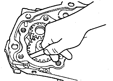
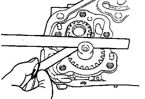
Fig. 13 Measuring Oil Pump Gear Side Clearance:
1. Inspect front case for cracks or damage, counter balance shaft front bearing section for wear, damage or seizure and oil holes for clogging.
2. Inspect counter balance shafts journals for wear or seizure.
3. Assemble oil pump gear to front case and rotate gear to ensure smooth rotation with no looseness.
4. Inspect contact surface between front case and gear surface of oil pump cover, ensuring there is no ridge wear.
5. With drive and driven gears installed, measure tip clearance of gears, Fig. 12, then side clearance, Fig. 13. If not within specifications, replace.
Installation
1. If necessary, install counter balance shafts bearings as follows:
a. Apply engine oil to outer surface of left rear bearing and bearing bore in cylinder block, Then install left counter balance shaft rear bearing into cylinder block using counter balance shaft bearing installer 09212-32200 and guide plate 09212-32300 or their equivalents.
b. Apply engine oil to outer surface of right rear bearing and bearing bore in cylinder block, then install right counter balance shaft rear bearing into cylinder block using counter balance shaft bearing installer 09212-32200 or equivalent.
c. Install right front counter balance shaft bearing into cylinder block using counter balance shaft bearing installer 09212-32200 or equivalent. Ensure bearing oil hole is aligned with oil hole of cylinder block.
2. Apply engine oil to oil pump gears and install into case aligning two timing marks.
3. Install crankshaft front oil seal into case using crankshaft front oil seal installer 09214-32000 or equivalent.
4. Place crankshaft front oil seal guide 09214-32100 or equivalent on front end of crankshaft and apply a thin coat of engine oil to outer circumference of guide.
5. Install front case assembly and tighten bolts to specifications.
6. Insert screwdriver through plug hole in left side of cylinder block to hold left counter balance shaft in position, then tighten oil pump sprocket bolt to specifications.
7. Install plug cap to case and tighten to specifications.
Fig. 30 Applying Sealer To Oil Pan Flange:
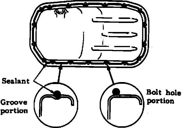
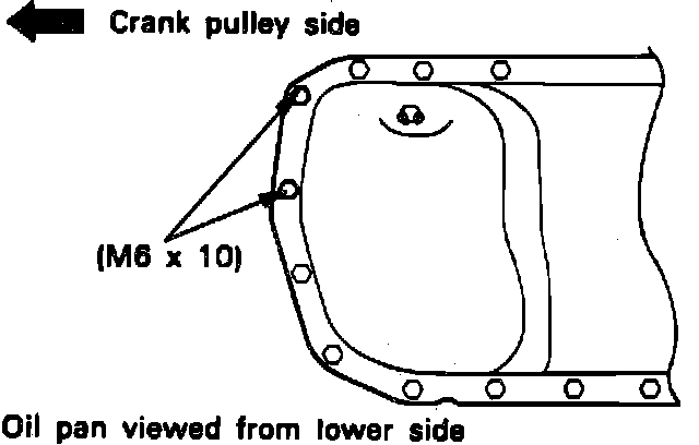
Fig. 15 Oil Pan Bolt Identification:
8. Apply sealant into groove of oil pan flange as shown in Fig. 14, in an approximate .16 inch thickness. Do not exceed 15 minutes before installing pan.
9. Note difference in bolt lengths at locations shown in Fig. 15, then install oil pan and tighten bolts to specifications.
10. Apply Threebond 1104 or equivalent to threads of oil pressure switch, then install switch tightening to specifications using oil pressure switch wrench 09260-32000 or equivalent.