Rear
Replacement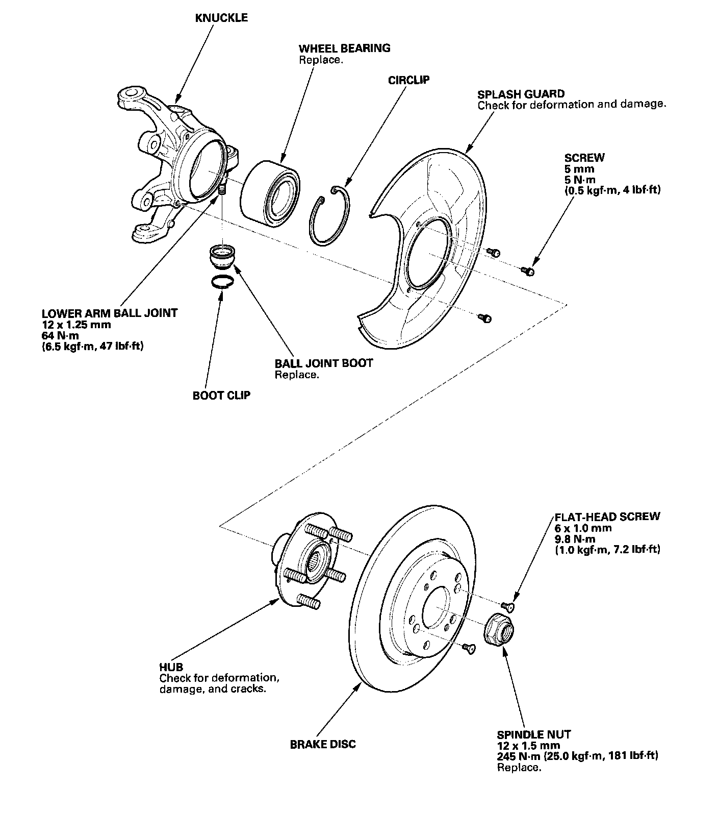
Special Tools Required
- Hub dis/assembly tool attachment, 42 mm 07GAFSD40100
- Ball joint remover, 28 mm 07MAC-SL00200
- Bearing driver attachment, 62 x 68 mm 07746-001050
- Driver, 07749-0010000
- Support base, 72 x 78/82.6 mm 07965-SD90100
- Attachment, 52 x 55 mm 07746-0010400
1. Loosen the wheel nuts slightly.
2. Raise the rear of the vehicle, and make sure it is securely supported.
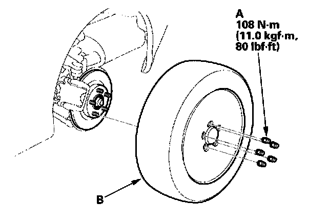
3. Remove the wheel nuts (A) and rear wheel (B).
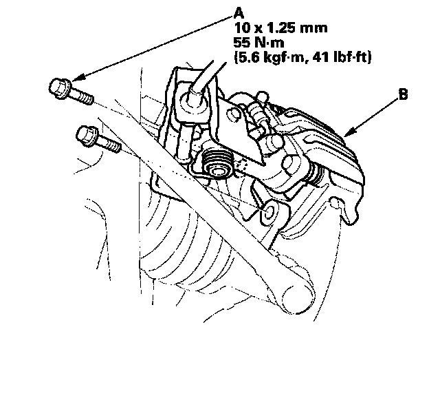
4. Remove the caliper bracket mounting bolts (A), and remove the caliper assembly (B) from the knuckle. To prevent damage to the caliper assembly or brake hose, use a short piece of wire to hang the caliper assembly from the undercarriage. Do not twist the brake hose with force.
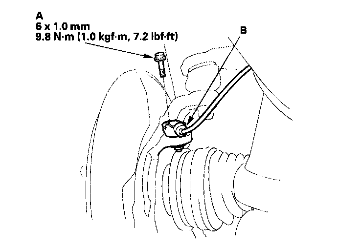
5. Remove the flange bolt (A) and wheel sensor (B) from the knuckle. Do not disconnect the wheel sensor connector.
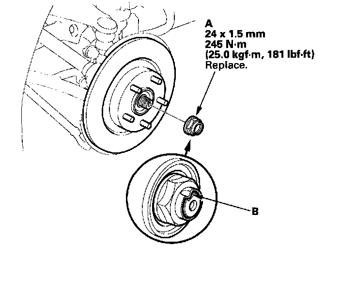
6. Raise the stake (A) of the spindle nut (B), and remove the nut.
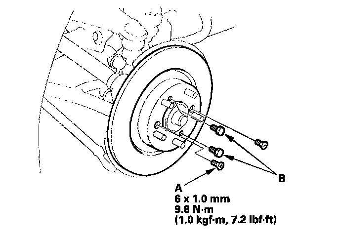
7. Remove the 6 mm brake disc retaining flat-head screws (A).
8. Screw two 8 x 1.25 mm bolts (B) into the disc to push it away from the hub. Turn each bolt two turns at a time to prevent cocking the disc excessively.
9. Remove the brake disc from the knuckle.
10. Check the hub for damage and cracks.
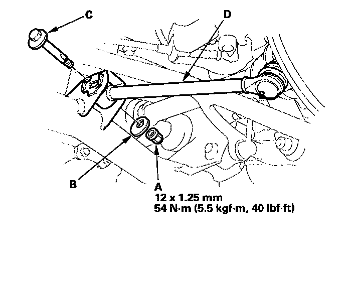
11. Remove the self-locking nut (A), cam plate (B), and adjusting bolt (C), then disconnect the control arm (D) from the frame.
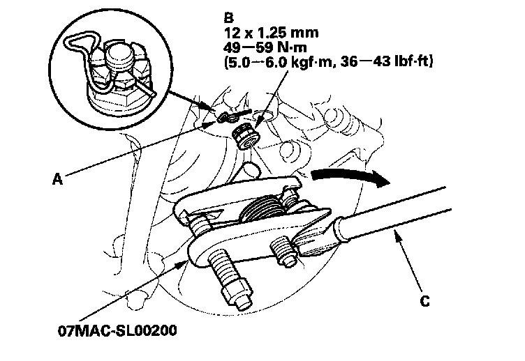
12. Remove the clip (A) from the control arm ball joint, and remove the castle nut (B).
13. Remove the control arm ball joint from the knuckle using the special tool.
NOTE: Turn the control arm (C) outward to install the ball joint remover.
14. Remove the control arm.
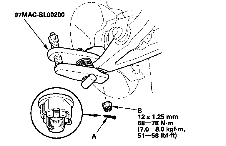
15. Remove the cotter pin (A) from the lower arm ball joint, and remove the castle nut (B).
16. Remove the lower arm ball joint from the knuckle using the special tool.
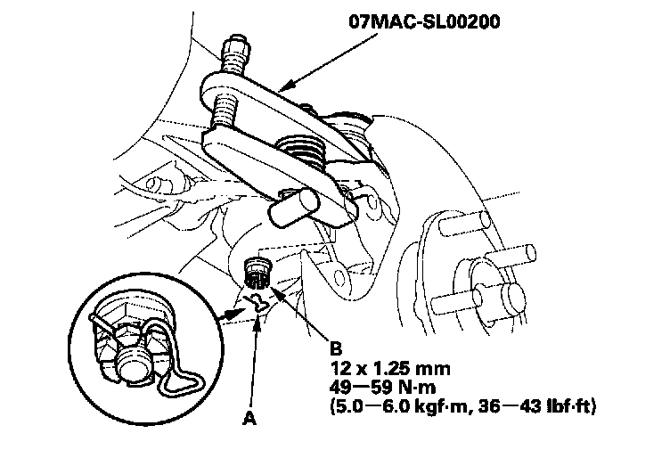
17. Remove the clip (A) from the upper arm ball joint, and remove the castle nut (B).
18. Remove the upper arm ball joint from the knuckle using the special tool.
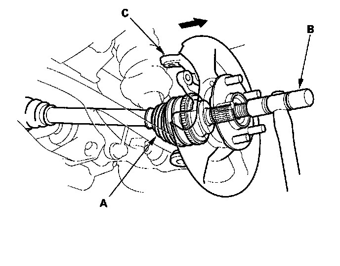
19. Remove the driveshaft outboard joint (A) from the knuckle by tapping the driveshaft end with a plastic hammer (B) while pulling the knuckle (C) outward.
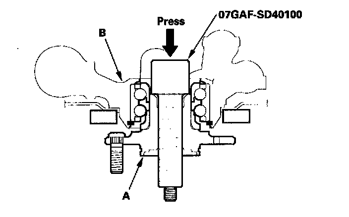
20. Separate the hub (A) from the knuckle (B) using the special tool and a hydraulic press. Take care not to deform the splash guard. Hold the hub to keep it from falling when pressed clear.
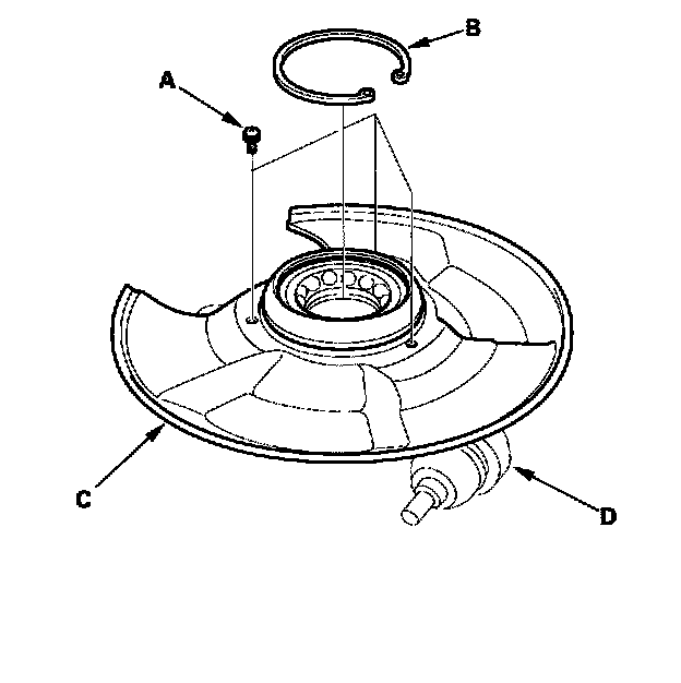
21. Remove the screws (A), circlip (B), and the splash guard (C) from the knuckle (D).
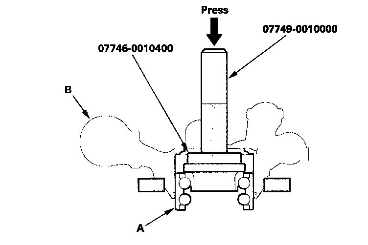
22. Press the wheel bearing (A) out of the knuckle (B) using the special tools and a press.
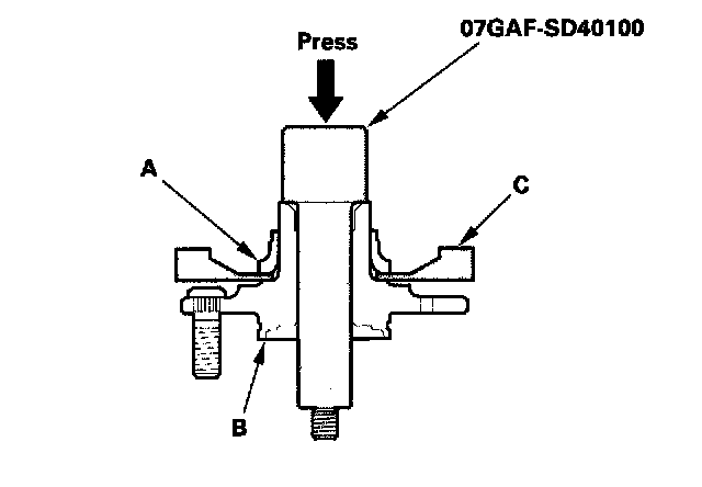
23. Press the wheel bearing inner race (A) out of the hub (B) using the special tool, a commercially available bearing separator (C), and a press.
24. Wash the knuckle and hub thoroughly in high flash point solvent before reassembly.
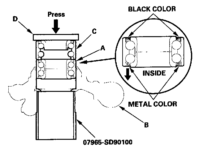
25. Press a new wheel bearing (A) into the knuckle (B) using the old bearing (C), a steel plate (D), the special tool, and a press. Place the wheel bearing on the knuckle with the pack seal side (metal color) facing inside. Be careful not to damage the sleeve of the pack seal.
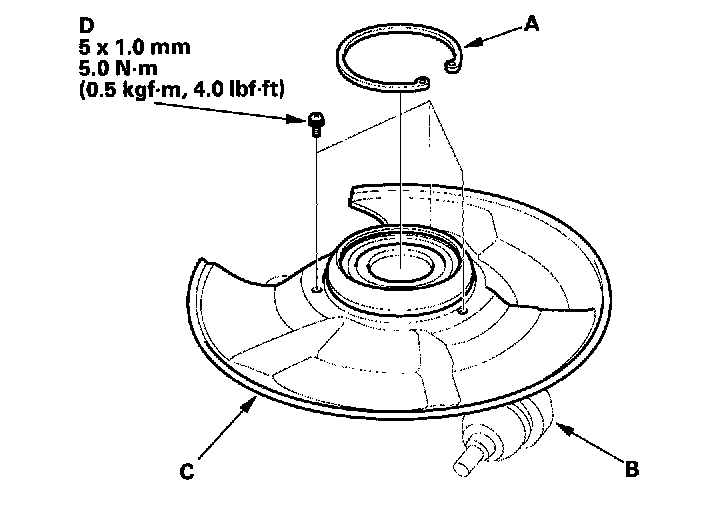
26. Install the circlip (A) securely in the knuckle (B).
27. Install the splash guard (C), and tighten the screws (D).
28. Wash the hub thoroughly in high flash point solvent before reassembly.
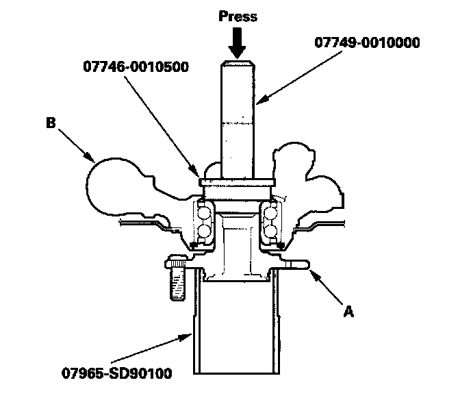
29. Install the hub (A) onto the knuckle (B) using the special tools and a hydraulic press. Take care not to deform the splash guard.
30. Install the knuckle in the reverse order of removal paying particular attention to the following items:
- Be careful not to damage the ball joint boot when installing the knuckle.
- Use a new spindle nut on reassembly.
- Before installing the spindle nut, apply a small amount of engine oil to the seating surface of the nut. After tightening, use a drift to stake the spindle nut shoulder against the driveshaft.
- Tighten all mounting hardware to the specified torque values.
- Tighten the castle nut to the lower torque specification, then tighten only far enough to align the slot with the pin or clip hole. Do not align by loosening the castle nut.
- Install a new cotter pin or clip on the castle nut after torquing.
- Before installing the brake disc, clean the mating surface of the hub and the inside of the brake disc.
- Before installing the wheel, clean the mating surface of the brake disc and the inside of the wheel.
- Check the wheel alignment, and adjust it if necessary.