Thermal Vacuum Valve: Description and Operation
SPARK COOLANT TEMPERATURE OVERRIDE (CTO) SYSTEM
On some models, vacuum spark advance operates on carburetor ported vacuum after engine has reached operating temperature. While engine is warming up, driveability can be improved by operating the distributor vacuum spark advance with manifold vacuum while engine is cold. On 4-151 engines, the CTO switch is threaded into the bottom of the thermostat housing. On 4-151 engines, when coolant temperature is below 120 degrees F., manifold vacuum is routed through switch port 1 into port D allowing manifold vacuum to be applied to the distributor vacuum advance unit. On 4-151 engines, when coolant reaches the specified temperature, port 1 closes and port 2 is connected to port D applying carburetor ported vacuum to the distributor vacuum advance unit.
Fig. 34 Non-linear vacuum regulator valve:
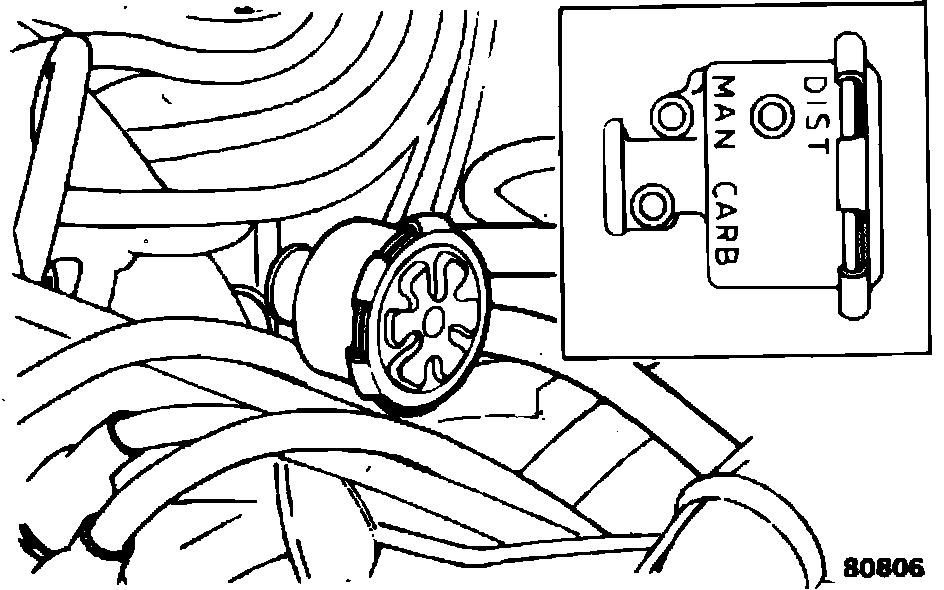
NON-LINEAR VACUUM REGULATION VALVE
The non-linear vacuum regulator (NLVR) Fig. 34, combines regulated vacuum at idle speed and carburetor ported vacuum to provide a regulated output signal to control the ignition spark advance mechanism. It is mounted in series between the vacuum source port and distributor vacuum advance unit. The NLVR has two input ports, intake manifold vacuum and carburetor ported vacuum, and one outlet port at the distributor advance unit. At curb idle, the NLVR provides regulated vacuum. Under these conditions, manifold vacuum is high and ported vacuum is either very low or non-existent. The NLVR, as determined by the calibration of the valve, provides a signal between the two vacuum levels. As engine load increases and the signal increases above the regulation point (7.5 in Hg @ 75° F ±5), the regulator valve switches to ported vacuum output.
THERMAL VACUUM SPARK CONTROL DELAY VALVE
On some models, this valve is added to the air cleaner to control vacuum between the intake manifold source and the spark CTO switch. The purpose of the valve is to allow the flow of controlled manifold vacuum when air passing through the air cleaner is below 63° F for 4-151 engines. At temperatures above this level, manifold vacuum is prevented from reaching the spark CTO until coolant temperature reaches the spark CTO switch point.
Fig. 43 Vacuum spark control delay valve:
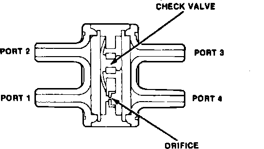
VACUUM SPARK CONTROL DELAY VALVE
On models equipped with 4-151 engine, a spark control delay valve, Fig. 43, is added to the vacuum advance circuit. The purpose of this valve is to provide improved driveability when the engine is cold. The valve uses a separate external thermal vacuum switch that connects ports 2 and 3 when the vacuum spark control delay valve is open. Ports 1 and 2 and 3 and 4 are connected internally.
Fig. 44 Vacuum solenoid valve:
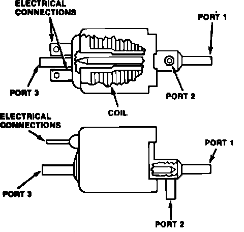
VACUUM SOLENOID VALVE
This electrically-operated solenoid valve, Fig. 44, is used on models with 4-151 engine, automatic transmission and air conditioning. The solenoid is energized when the A/C compressor clutch engages and switches the vacuum signal to the advance unit from manifold vacuum to carburetor ported vacuum. Ports 1 and 2 of the valve are connected when the solenoid is energized. Ports 3 and 4 of the valve are connected when the solenoid is de-energized and switches from carburetor ported vacuum to manifold vacuum.