Servo Unit Holding Coil & Low Speed Switch Test
Refer to "Speed Control Wiring Diagrams". Prior to performing any tests, ensure servo or valve body and electronic module are properly tested.Fig. 2 Speed control wiring diagram. 1980-84 Vans, Wagons & Front Sections:
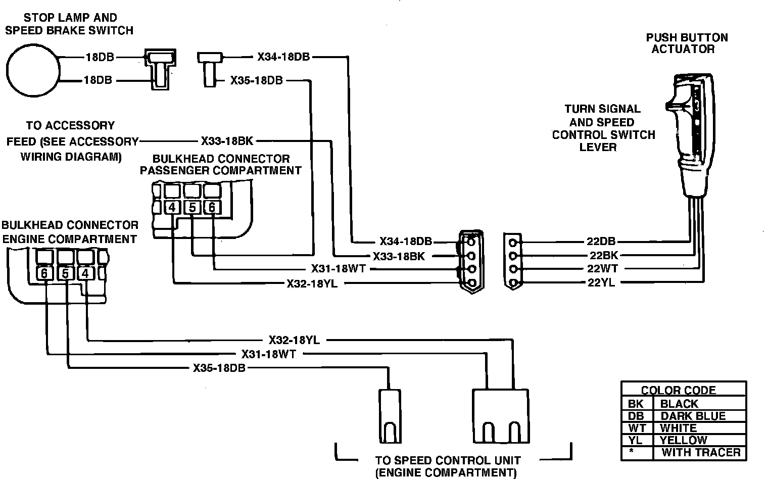
Fig. 3 Speed control wiring diagram. 1981-84 Ramcharger, Trail Duster & Conventional Cabs:
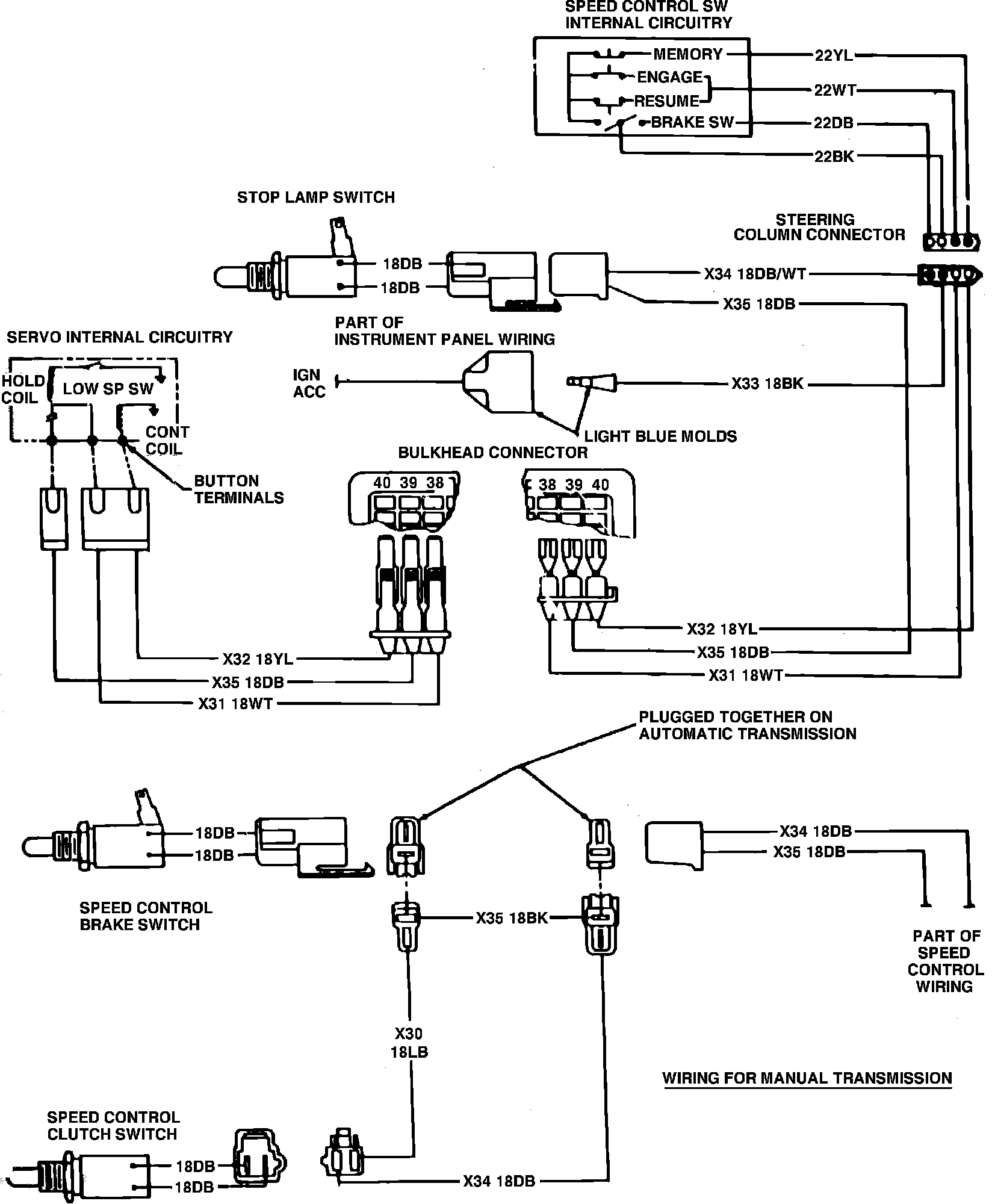
Fig. 4 Speed control wiring diagram. 1982-84 Rampage & 1983 Scamp:
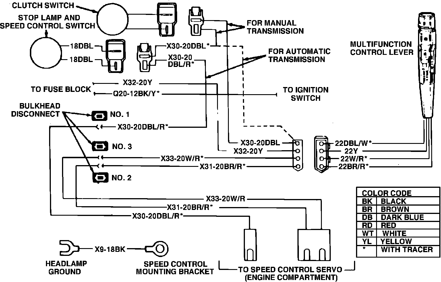
Fig. 7 Speed control wiring diagram. 1985 rear wheel drive Ram Van & Wagons:
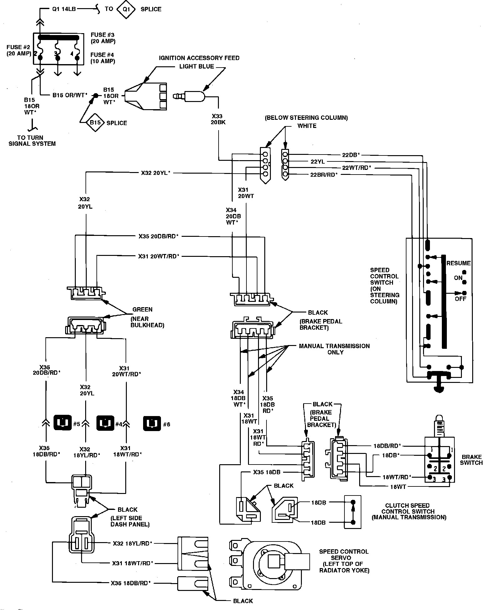
1982 Front Wheel Drive Models
1. Without removing either connector at servo, connect one test lead from a suitable test lamp to the white wire with red tracer, then connect the second test lead to ground.
2. Block rear wheels, then raise and support front of vehicle.
3. Place transmission selector lever or gear shift lever in driving range, then accelerate to approximately 35 mph with slide switch in "On" position.
4. Depress and release "Speed Set" button to engage speed control system. Test lamp should remain on until brake pedal is depressed, then test lamp should go off.
5. Remove test lamp.