Disassembly
VALVE BODYDISASSEMBLY
NOTE: If valve body assembly is being reconditioned, the PCM/TCM Quick Learn Procedure must be performed. ..
Fig. 408 Manual Shaft Seal:
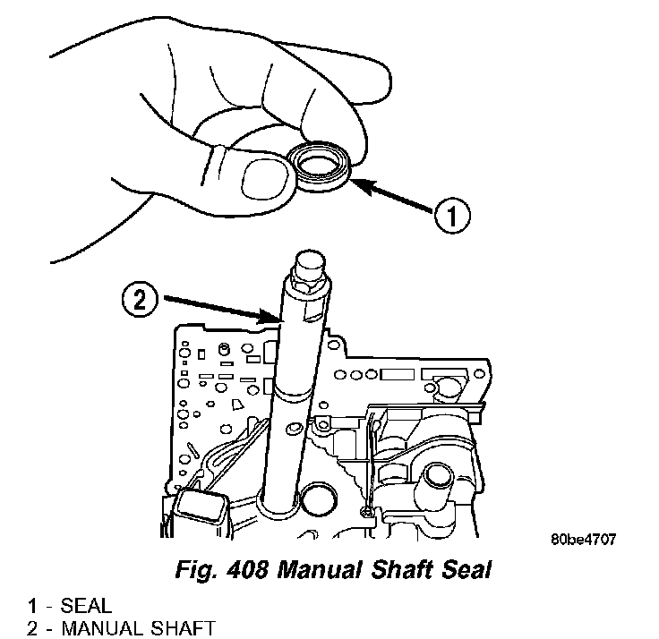
1. Remove manual shaft seal (1) (Fig. 408).
Fig. 409 Remove Transmission Range Sensor:
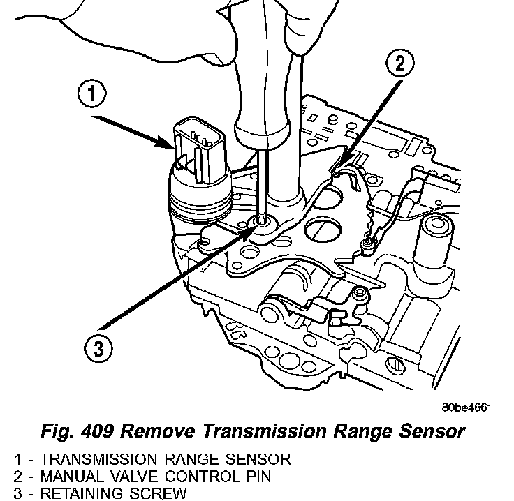
2. Remove Transmission Range Sensor retaining screw (3) (Fig. 409).
Fig. 410 Manual Shaft/Rooster Comb and Transmission Range Sensor:
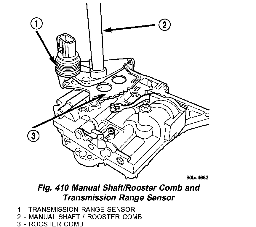
3. Remove Manual Shaft/Rooster Comb (3) (Fig. 410) and Transmission Range Sensor (1).
Fig. 411 2/4 Accumulator Retaining Plate:
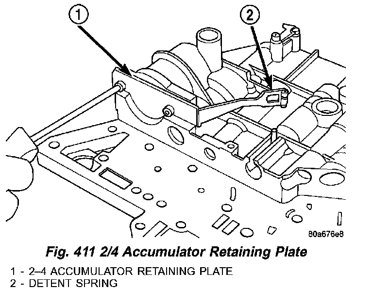
4. Remove 2/4 Accumulator Retaining Plate (1) (Fig. 411).
Fig. 412 2/4 Accumulator Assembly:
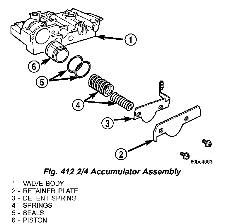
5. Remove 2/4 Accumulator components (2,3,4,5 and 6) (Fig. 412).
Fig. 413 Remove Valve Body to Transfer Plate Screws:
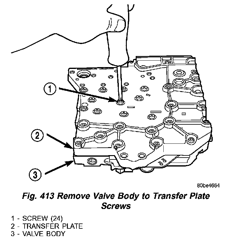
6. Remove Valve Body (3) (Fig. 413) to Transfer Plate (2) screws (1).
Fig. 414 Remove Transfer Plate:
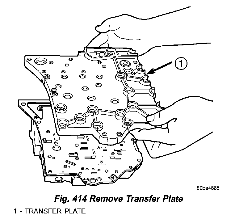
7. Invert assembly and remove Transfer Plate (1) (Fig. 414). Beware of loose check balls.
Fig. 415 Remove Oil Screen:
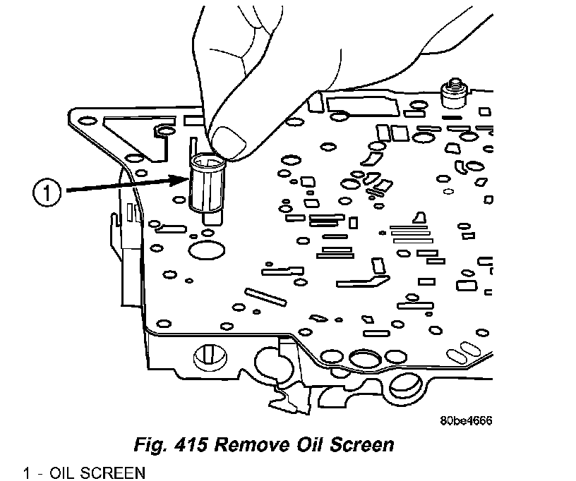
8. Remove oil screen (1) (Fig. 415).
Fig. 416 Remove Overdrive Clutch (#5) Check Valve:
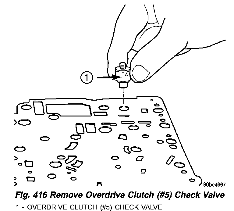
9. Remove the overdrive clutch (#5) check valve (1) (Fig. 416).
Fig. 417 Remove Separator Plate:
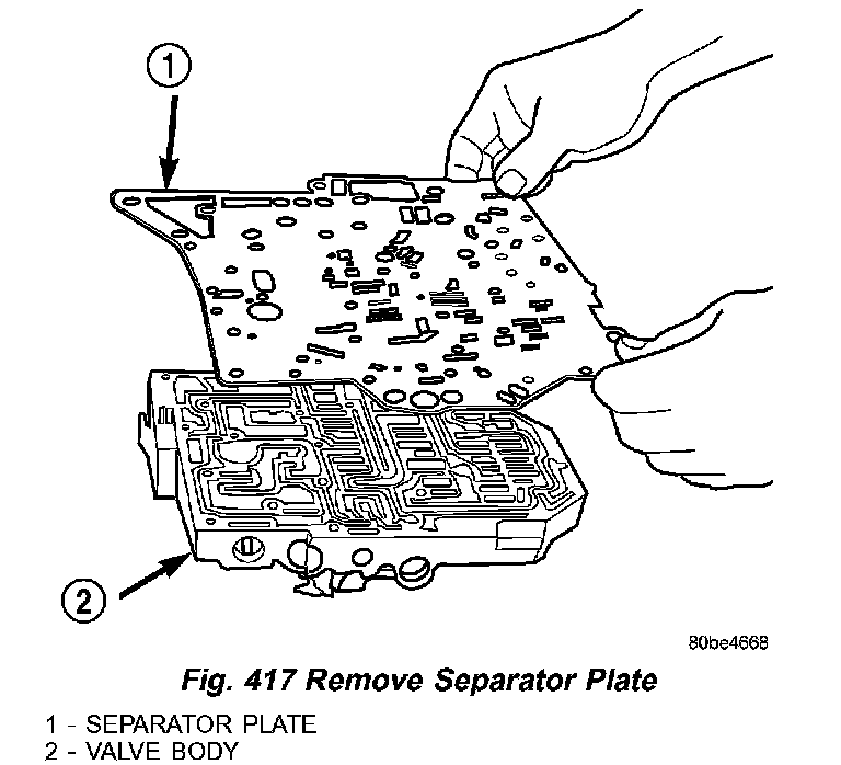
10. Remove separator plate (1) (Fig. 417).
Fig. 418 Remove Thermal Valve:
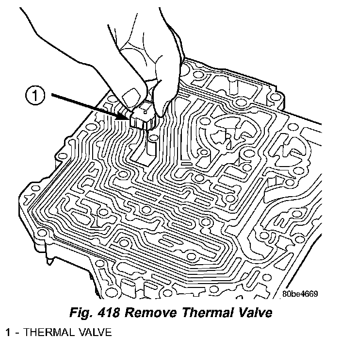
11. Remove thermal valve (1) (Fig. 418).
Fig. 419 Ball Check Location:
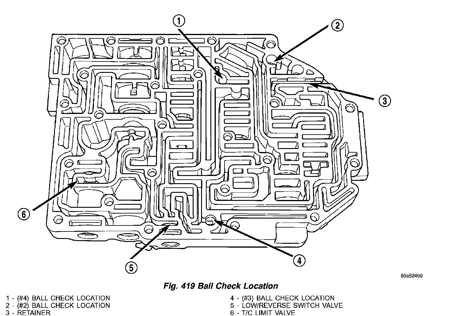
12. Remove check balls, (1) (Fig. 419) (#4) ball check location, (2) (#2) ball check location, (3) retainer, (4) (#3) ball check location, (5) low/reverse switch valve and (6) t/c limit valve.
NOTE: Tag all valve/spring assemblies for reassembly identification.
Fig. 420 Remove Dual Retainer Plate using Tool 6301:
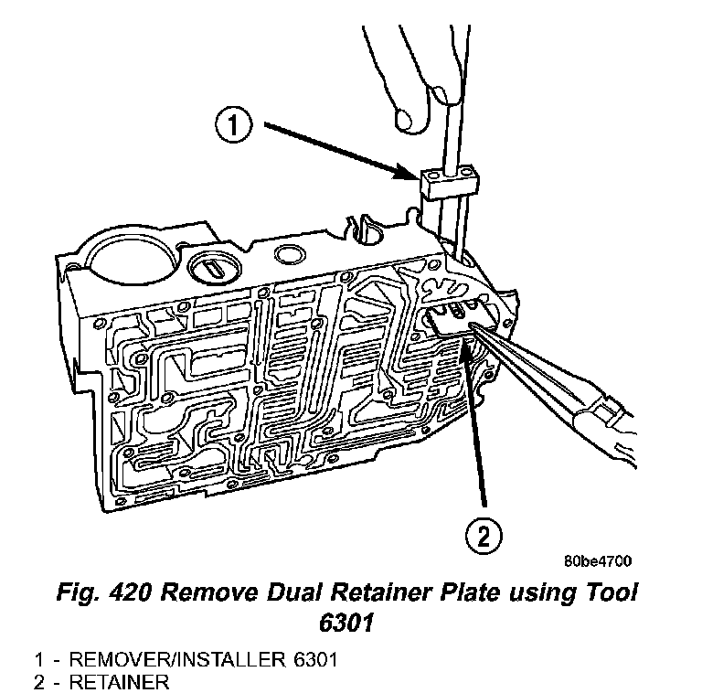
13. Remove dual retainer plate (2) (Fig. 420) using Remover/Installer 6301(l).
Fig. 421 Remove Regulator Valve Spring Retainer using Tool 6302:
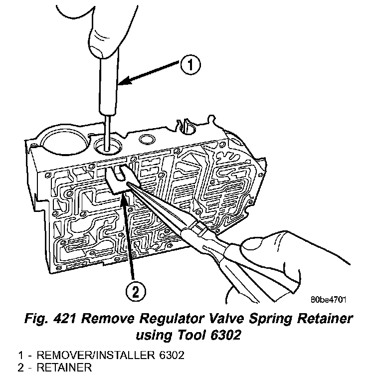
14. Remove regulator valve spring retainer (2) (Fig. 421) using Remover/Installer 6302 (1).
Fig. 422 Valve Retainer Location:
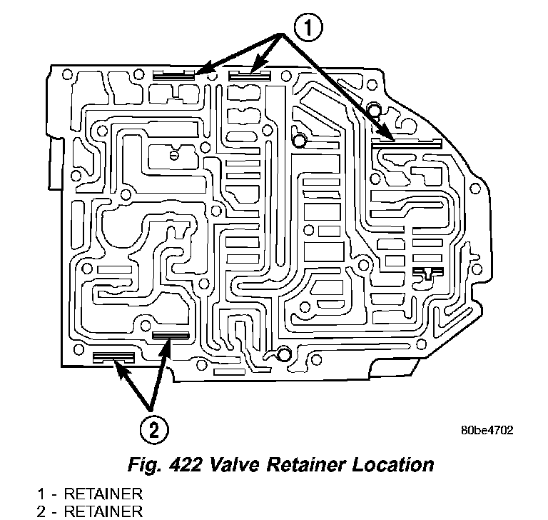
15. Remove remaining retainers (1,2) (Fig. 422).
Fig. 423 Springs and Valves Location:
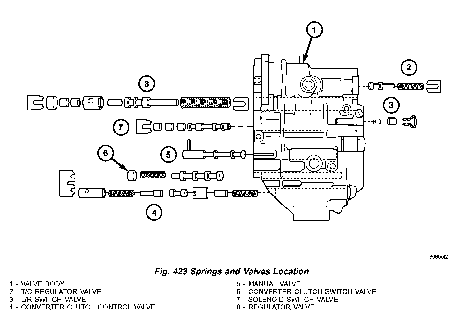
16. Remove valves and springs (Fig. 423).
NOTE: Refer to Valve Body Cleaning and Inspection for cleaning procedures.