Steering Column
COLUMNREMOVAL
NOTE: Before proceeding, Refer to Steering Column / Service Precautions.
1. Place front wheels of vehicle in STRAIGHT AHEAD position.
2. Disconnect and isolate the battery negative cable. Wait two minutes for the airbag system reserve capacitor to discharge before beginning any steering column, instrument panel, or airbag system/ component service.
WARNING: WHEN AN UNDEPLOYED AIRBAG IS TO BE REMOVED FROM THE VEHICLE, FIRST DISCONNECT AND ISOLATE THE BATTERY NEGATIVE (GROUND) CABLE. ALLOW THE AIRBAG SYSTEM RESERVE CAPACITOR TO DISCHARGE FOR TWO MINUTES BEFORE BEGINNING ANY AIRBAG SYSTEM OR COMPONENT SERVICE. PERSONAL INJURY MAY RESULT IF THIS PROCEDURE IS NOT FOLLOWED.
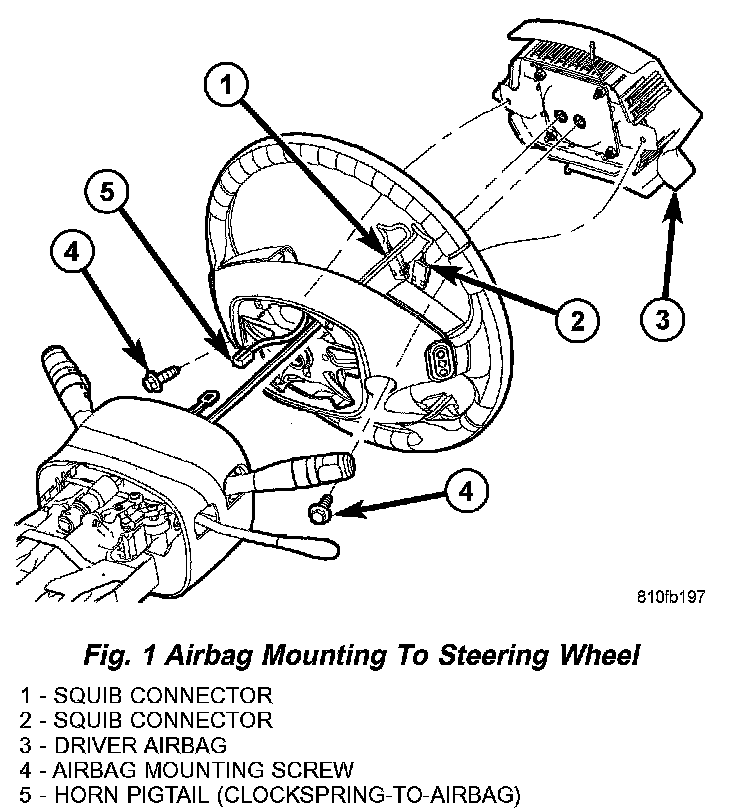
3. Remove driver airbag mounting screws (Fig. 1).
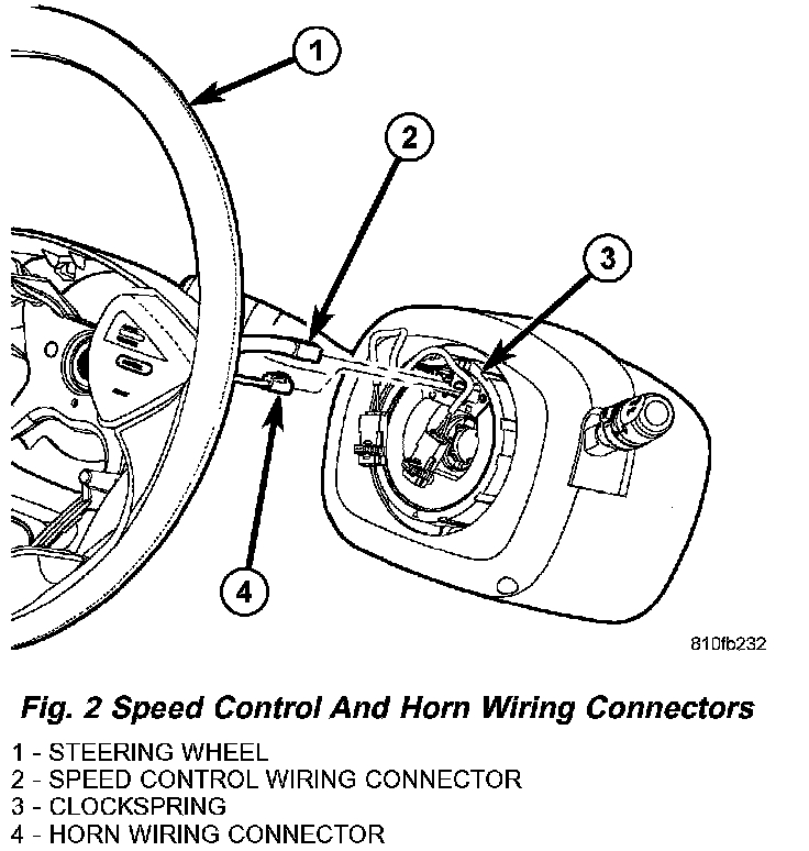
4. Lift airbag from mount and disconnect two airbag squib connectors and horn connector (Fig. 1) (Fig. 2). Remove driver airbag.
5. Disconnect speed control wiring connector at clockspring (center terminal) (Fig. 2).
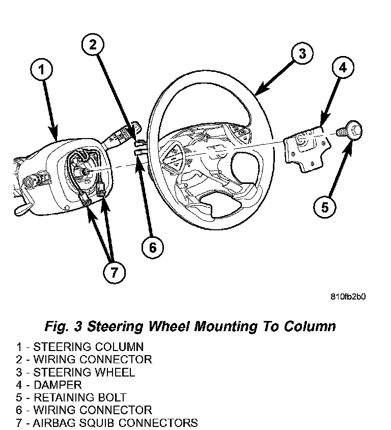
6. Remove steering wheel retaining nut (Fig. 3).
7. Remove damper (Fig. 3).
8. Remove steering wheel using standard wheel puller.
9. Access and remove knee blocker airbag.
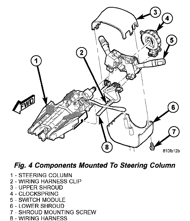
10. Remove three screws fastening lower shroud to upper shroud and column (Fig. 4).
11. Using hands, gently press inward at seams between shrouds at points where inner locking tabs exist, unlocking tabs (Fig. 4).
12. Remove upper, then lower shroud.
13. Remove column wiring harness routing clip from left side of column (Fig. 4).
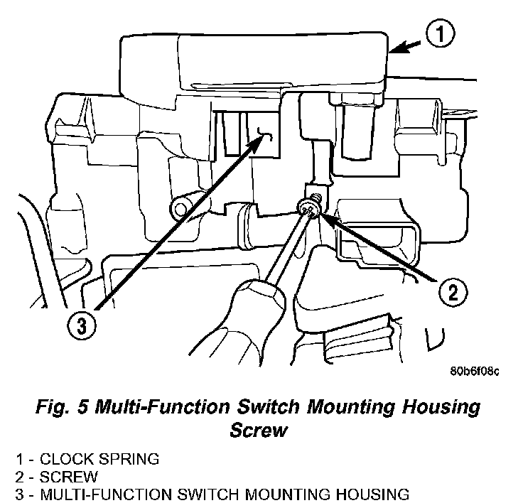
14. Remove screw on bottom of column (Fig. 5), then slide multi-function switch housing (with switches and clockspring) off column.
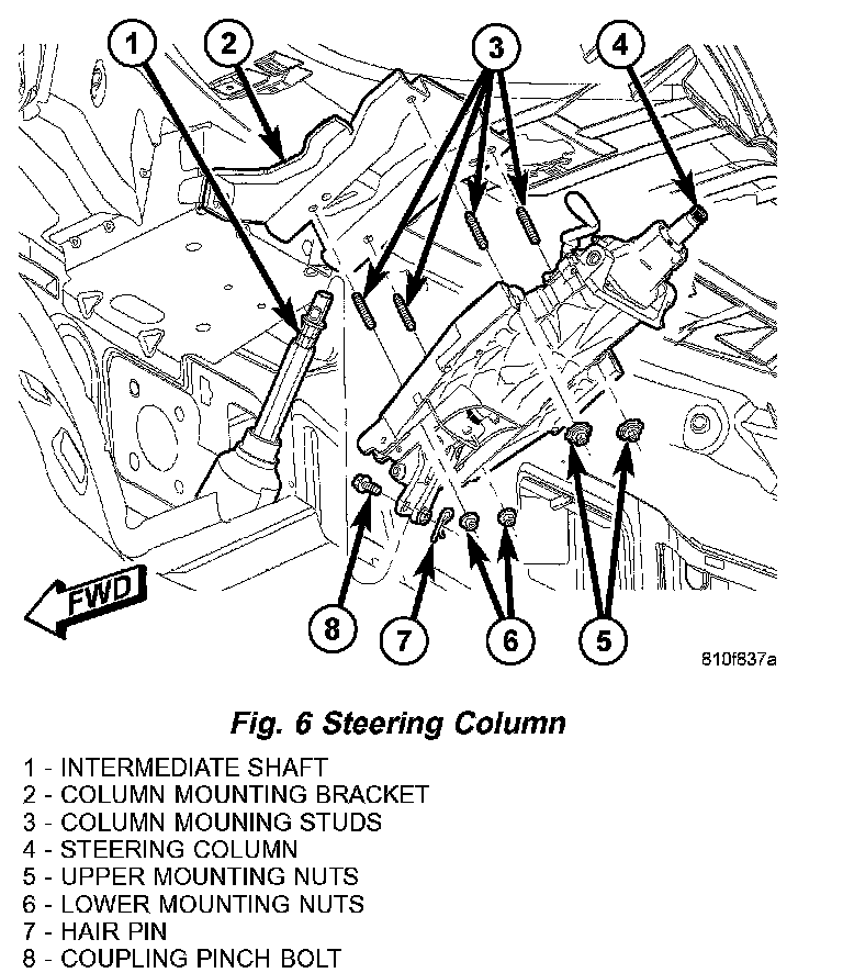
15. Disconnect steering column coupling at intermediate shaft (Fig. 6). To do so:
a. Remove hair pin at end of coupling pinch bolt.
b. Loosen nut and remove pinch bolt.
c. Remove intermediate shaft from coupling.
16. Remove four nuts fastening column to dash (Fig. 6). Remove column.
INSTALLATION
1. Place steering column over mounting studs and install four nuts fastening column to dash (Fig. 6). Tighten nuts to 12 Nm (105 inch lbs.) torque.
2. Connect steering column coupling to intermediate shaft (Fig. 6). To do so:
a. Match intermediate shaft to coupling pinch loop.
b. Install coupling pinch bolt. Tighten to 28 Nm (21 ft. lbs.) torque.
c. Install hair pin at end of pinch bolt.
3. Slide multi-function switch mounting housing onto column and install mounting screw. Tighten screw to 1.9 Nm (17 inch lbs.) torque.
4. Install column wiring harness routing clip into left side of column (Fig. 4).
5. Install lower and upper shrouds around column (Fig. 4):
a. Snap shrouds together at locking tab locations on both sides.
b. Install center mounting screw securing lower shroud to column. Tighten screw to 2 Nm (18 inch lbs.) torque.
c. Install two outer mounting screws securing lower shroud to upper shroud. Tighten screws to 2 Nm (18 inch lbs.) torque.
d. Inspect shroud mating surfaces for excessive gaps and adjust as necessary.
6. Install knee blocker airbag and all components necessary to access.
7. Match splines on steering wheel hub with that on steering shaft and slide steering wheel onto column shaft.
8. Install damper on steering wheel (Fig. 3).
9. Install steering wheel retaining bolt (Fig. 3). Tighten bolt to 61 Nm (45 ft. lbs.) torque.
10. Connect speed control wiring connector at clockspring (Fig. 2).
11. Connect two airbag squib connectors and horn connector to driver airbag (Fig. 1).
12. Place driver airbag on steering wheel and install mounting screws (Fig. 1). Tighten screws to 10 Nm (90 inch lbs.) torque.
13. Connect battery negative (-) cable to battery post following special Diagnosis And Testing procedure. Refer to Air Bag System / Testing and Inspection. Testing and Inspection
14. Check operation of all steering column mounted components.
15. Road test vehicle to ensure operation of steering.