Suction Hose Replacement
Suction Hose Replacement (LFX)
Special Tools
J 39400-A Halogen Leak Detector
Removal Procedure
Note:
With the ignition OFF and the brakes cool, apply the brakes 3-5 times, or until the brake pedal becomes firm, in order to deplete the vacuum brake booster power reserve.
1. Deplete the vacuum brake booster power reserve.
Warning:
Refer to Safety Glasses Warning Safety Glasses Warning.
2. Recover the refrigerant. Refer to Refrigerant Recovery and Recharging Refrigerant Recovery and Recharging.
Warning:
Refer to Battery Disconnect Warning Battery Disconnect Warning.
3. Disconnect the battery negative cable. Refer to Battery Negative Cable Disconnection and Connection (Primary) Battery Negative Cable Disconnection and Connection (Primary)Battery Negative Cable Disconnection and Connection (Auxiliary) Battery Negative Cable Disconnection and Connection (Auxiliary).
4. Remove the air cleaner assembly. Refer to Air Cleaner Assembly Replacement Service and Repair.
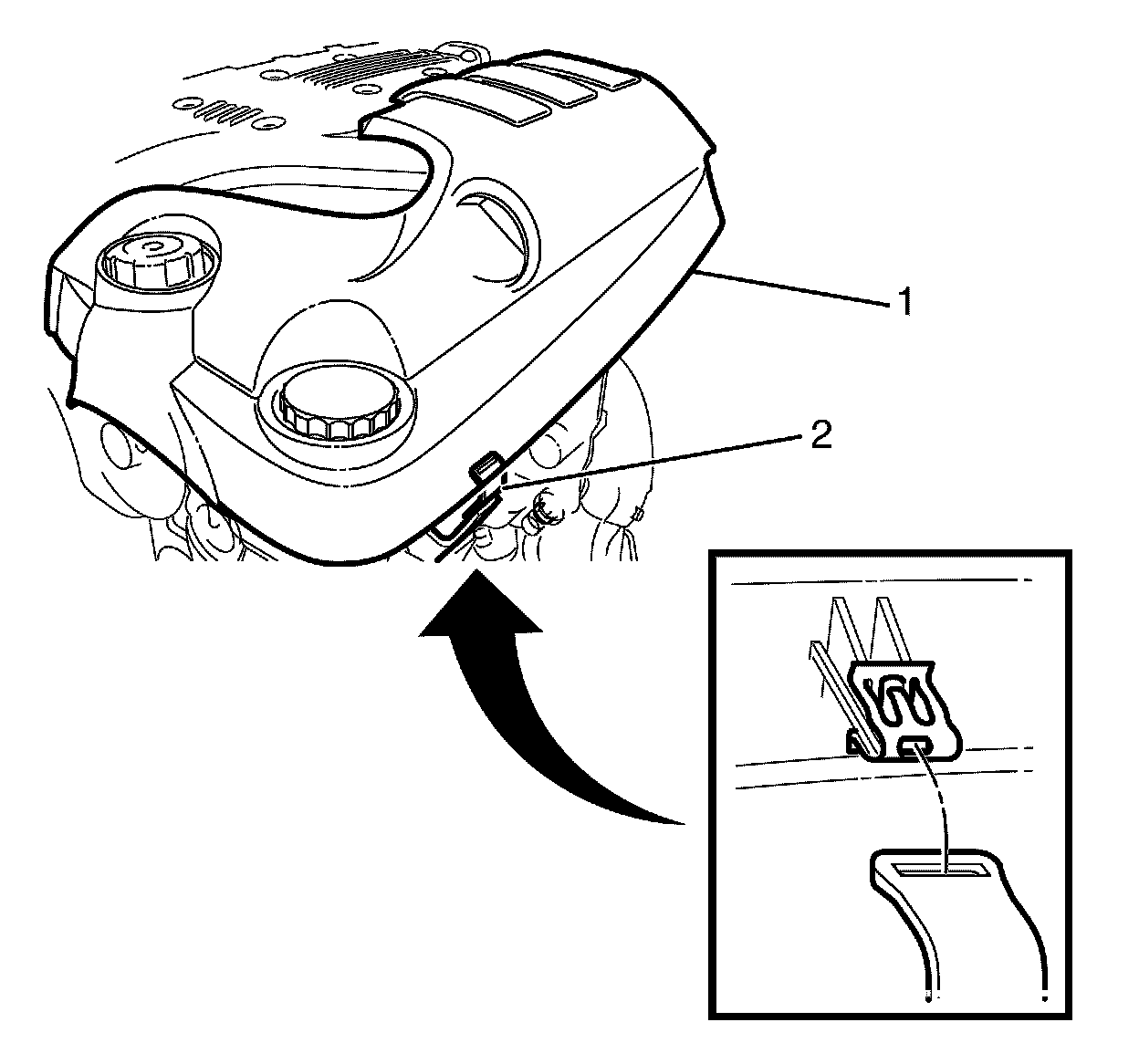
Note:
The left engine cover has one front and one rear outer retaining clip.
Note:
Grasp and pry the left engine cover (1) upwards to detach the left engine cover (1) from the outer retaining clip (2).
5. Detach the left engine cover (1) from the outer retaining clip (2).
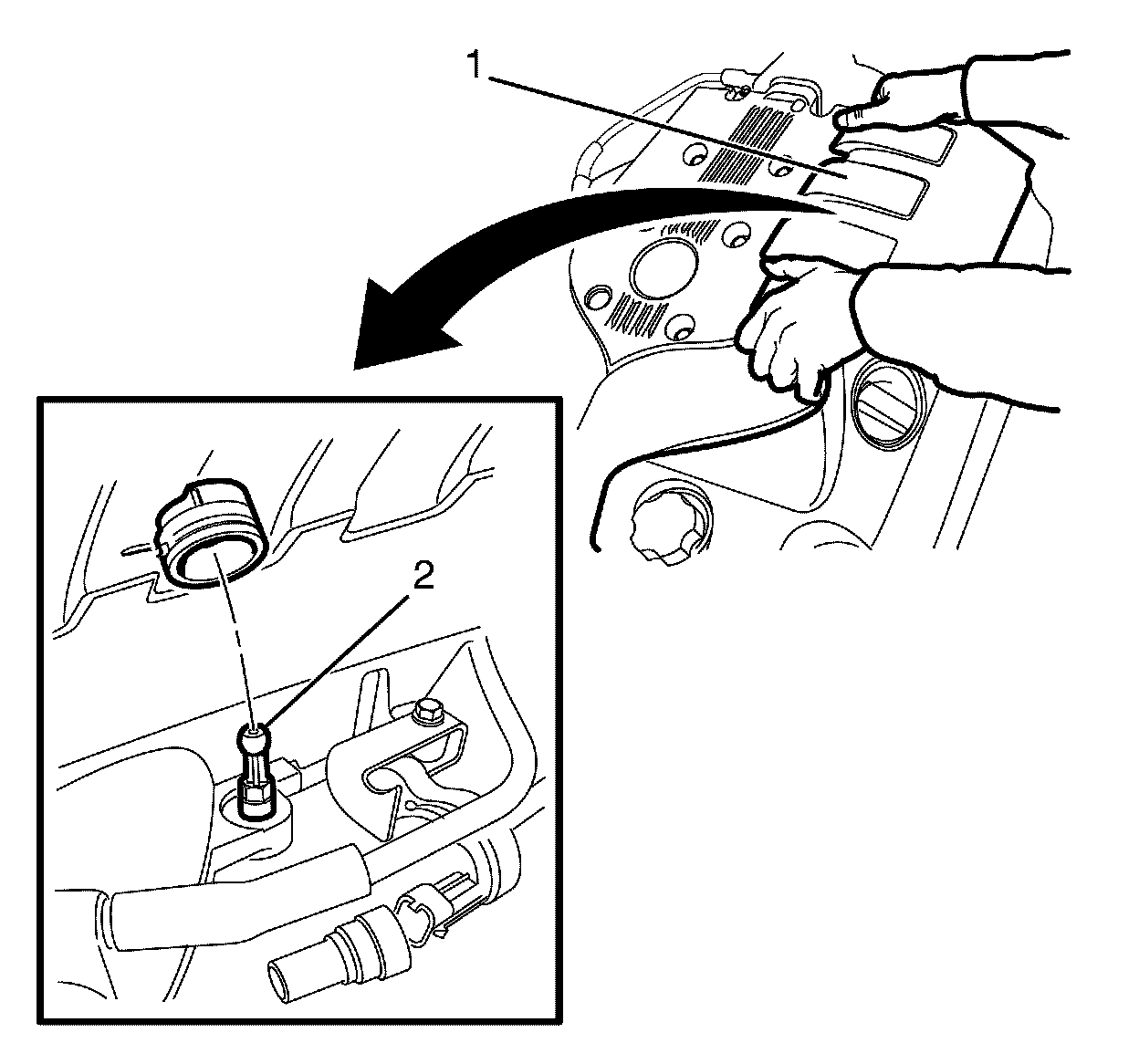
Note:
Disengage the left engine cover (1) from the ball stud (2) by pulling up firmly on the rear and front of the left engine cover (1).
6. Detach the left engine cover (1) from the ball stud (2).
7. Remove the left engine cover (1).
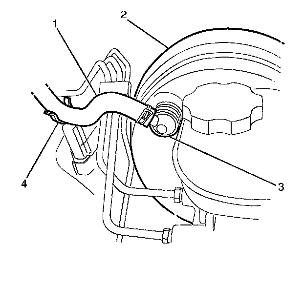
8. Disconnect the vacuum hose (1) and the vacuum brake booster check valve (3) from the vacuum brake booster (2).
9. Detach the vacuum hose (1) from the bulkhead mounted vacuum hose retaining bracket (4) and position aside.
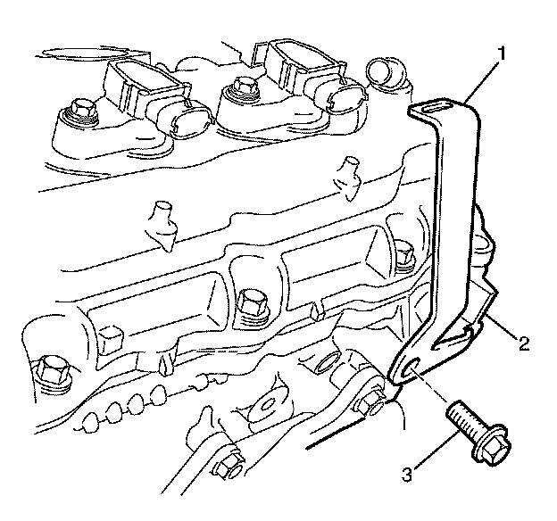
10. Remove the left engine cover mounting bracket to cylinder head retaining bolt (3).
11. Remove the left engine cover mounting bracket (1) from the cylinder head (2).
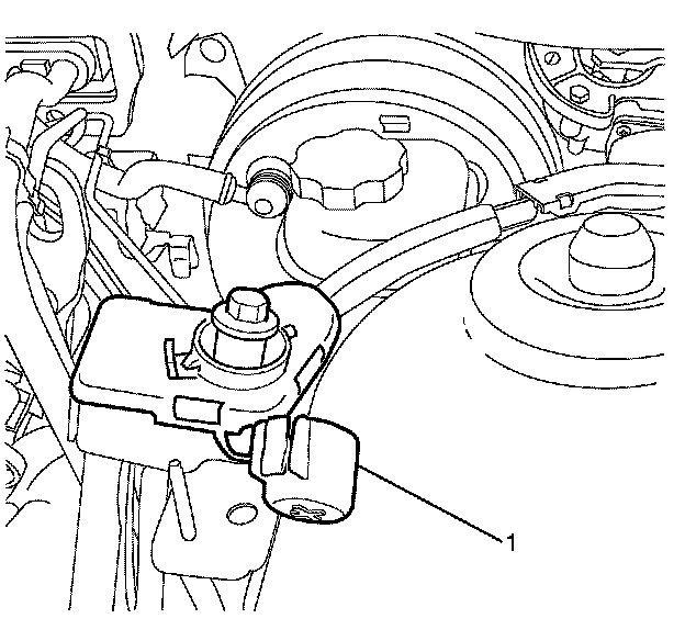
12. Remove the remote battery positive post cover (1).
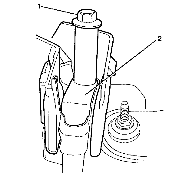
13. Remove the remote battery positive post to wiring harness retaining bolt (1).
14. Remove the starter motor power cable (2) and position aside.
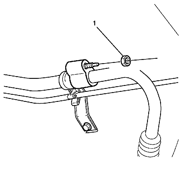
15. Remove the suction pipe upper to suction pipe lower retaining nut (1).
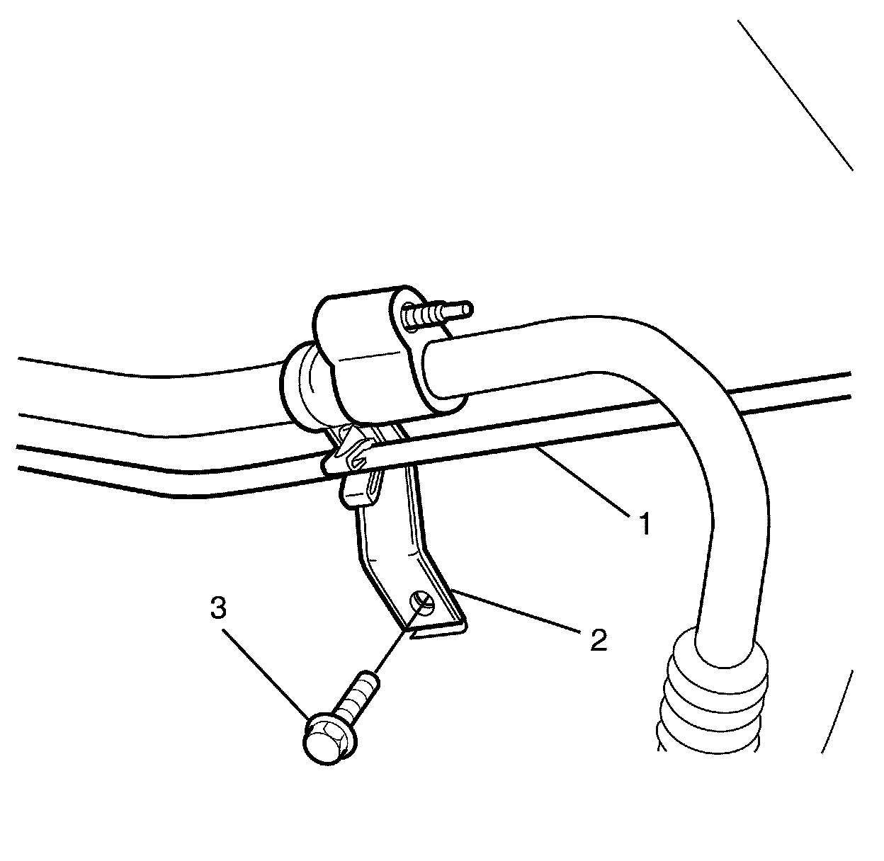
16. Remove the suction pipe/liquid pipe retaining clip to left front chassis rail retaining bolt (3).
17. Detach the liquid pipe (1) from the suction pipe/liquid pipe retaining clip (2).
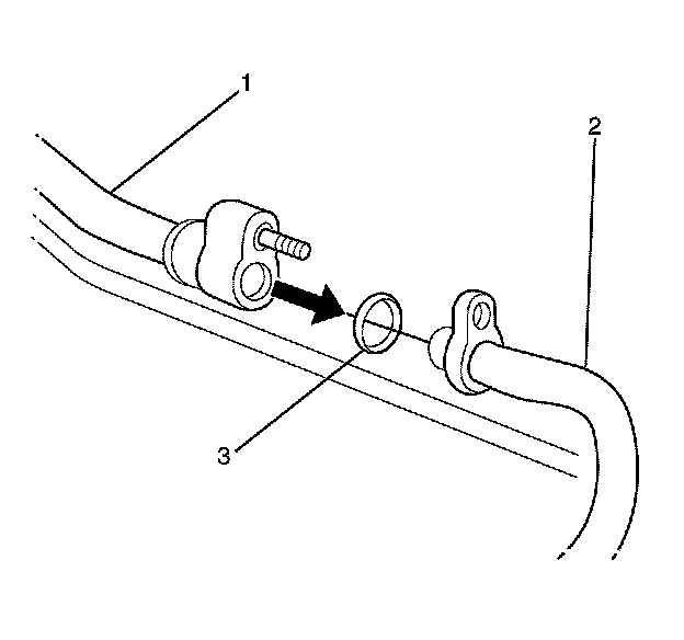
18. Disconnect the suction pipe upper (1) from the suction pipe lower (2).
Note:
The sealing washer (3) is a single use item and must be discarded after use.
19. Remove the sealing washer (3). Refer to Air Conditioning System Seal Replacement Air Conditioning System Seal Replacement.
Discard the sealing washer
Note:
Cover any opening of the A/C system with a suitable cap or tape immediately, to prevent absorption of moisture from the atmosphere.
20. Cap or plug the suction pipe upper (1) and the suction pipe lower (2).
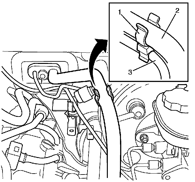
21. Detach the suction pipe (2) and the liquid pipe (3) from the suction pipe/liquid pipe retaining clip (1).
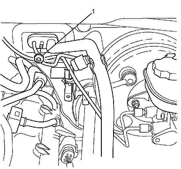
22. Remove the suction pipe/liquid pipe pad to TX valve retaining nut (1).
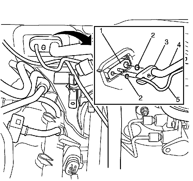
23. Disconnect the suction pipe/liquid pipe pad (3) from the TX valve (1).
Note:
The sealing washers (2) are a single use item and must be discarded after use.
24. Remove the sealing washers (2). Refer to Air Conditioning System Seal Replacement Air Conditioning System Seal Replacement.
Discard the sealing washers
Note:
Cover any opening of the A/C system with a suitable cap or tape immediately, to prevent absorption of moisture from the atmosphere.
25. Cap or plug the suction pipe (4), liquid pipe (5) and the TX valve (1).
26. Remove the liquid pipe (5) from the suction pipe/liquid pipe pad (3).
27. Remove the suction pipe/liquid pipe pad (3) from the engine compartment.
Installation Procedure
1. Install the liquid pipe (5) to the suction pipe/liquid pipe pad (3).
2. Remove the plugs or caps from the suction pipe (4), liquid pipe (5) and the TX valve (1).
Note:
DO NOT coat the NEW sealing washers (2) with oil, they must be fitted dry. The use of mineral oil will render the sealing washers (2) useless, as the sealing washers (2) WILL swell causing refrigerant to leak out.
3. Install NEW sealing washers (2). Refer to Air Conditioning System Seal Replacement Air Conditioning System Seal Replacement.
4. Position the suction pipe/liquid pipe pad (3) to the TX Valve (1).
Caution:
Refer to Fastener Caution Fastener Caution.
5. Install the suction pipe/liquid pipe pad to TX valve retaining nut (1) and tighten to 22 Nm (16 lb ft).
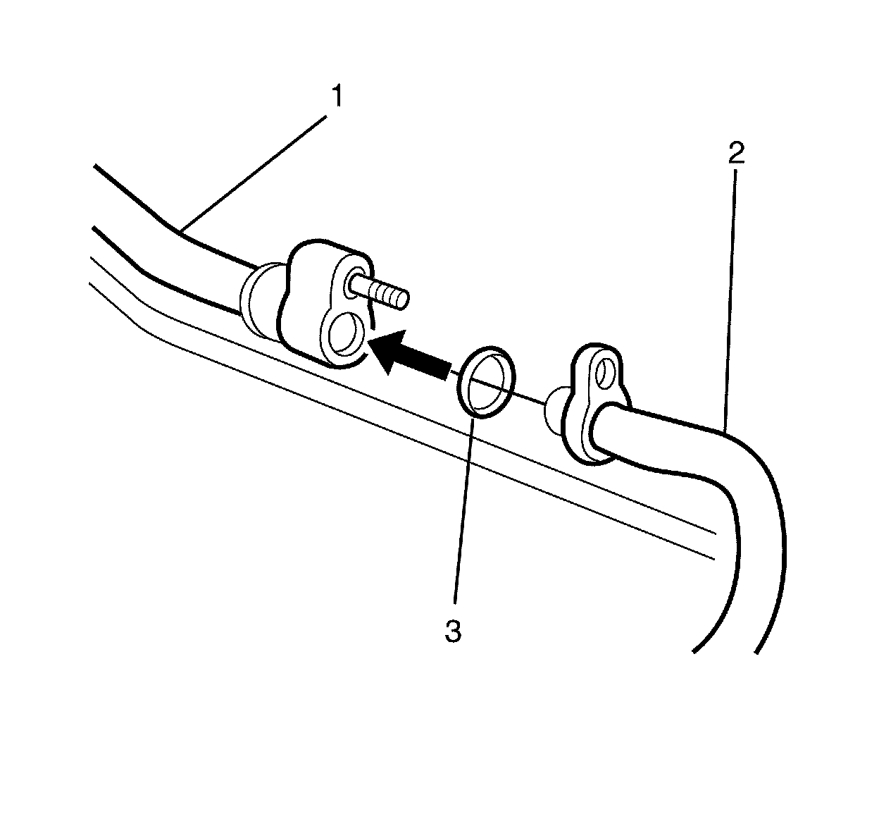
6. Remove the plugs or caps from the suction pipe upper (1) and the suction pipe lower (2).
Note:
DO NOT coat the NEW sealing washer (3) with oil, they must be fitted dry. The use of mineral oil will render the sealing washer (3) useless, as the sealing washer (3) WILL swell causing refrigerant to leak out.
7. Install a NEW sealing washer (3). Refer to Air Conditioning System Seal Replacement Air Conditioning System Seal Replacement.
8. Install the suction pipe upper (1) to the suction pipe lower (2).
9. Attach the liquid pipe (1) to the suction pipe/liquid pipe retaining clip (2).
10. Install the suction pipe/liquid pipe retaining clip to left front chassis rail retaining bolt (3) and tighten to 22 Nm (16 lb ft).
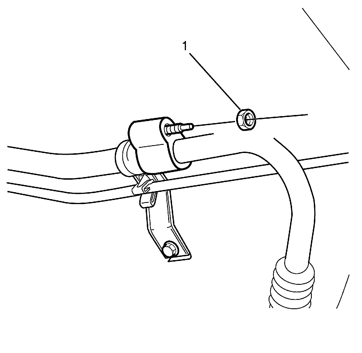
11. Install the suction pipe upper to suction pipe lower retaining nut (1) and tighten to 18 Nm (13 lb ft).
12. Install the starter motor positive cable (2) to the remote battery positive post.
13. Install the remote battery positive post to wiring harness retaining bolt (1) and tighten to 15 Nm (11 lb ft).
Note:
Make sure the clips on the remote battery positive post cover (1) are engaged to avoid an induced rattle condition.
14. Install the remote battery positive post cover (1).
15. Attach the suction pipe (2) and the liquid pipe (3) to the suction pipe/liquid pipe retaining clip (1).
16. Connect the vacuum hose (1) and the vacuum brake booster check valve (3) to the vacuum brake booster (2).
17. Attach the vacuum hose (1) to the bulkhead mounted vacuum hose retaining bracket (4).
18. Install the left engine cover mounting bracket (1) to the cylinder head (2).
19. Install the left engine cover mounting bracket to cylinder head retaining bolt (3) and tighten to 58 Nm (43 lb ft).
20. Position the left engine cover (1) over the intake manifold so the grommet is aligned with the ball stud (2).
Note:
Press the left engine cover (1) down firmly near the ball stud to attach the left engine cover (1) to the ball stud (2).
21. Attach the left engine cover (1) to the ball stud (2).
Note:
The left engine cover has one front and one rear outer retaining clip.
Note:
Press the left engine cover (1) down firmly near the outer retaining clips to attach the left engine cover (1) to the outer retaining clip (2).
22. Attach the left engine cover (1) to the outer retaining clip (2).
Note:
The receiver and dehydrator is a single use only component. A NEW receiver and dehydrator must be installed whenever a closed A/C system is opened or exposed to atmosphere. If the receiver and dehydrator has been replaced following a service/repair and it is deemed necessary to immediately re-open the A/C system it is not necessary to replace the receiver and dehydrator again, providing the A/C system is plugged/capped correctly.
23. Replace the receiver and dehydrator. Refer to Receiver and Dehydrator Replacement Service and Repair.
24. Install the air cleaner assembly. Refer to Air Cleaner Assembly Replacement Service and Repair.
25. Connect the battery negative cable. Refer to Battery Negative Cable Disconnection and Connection (Primary) Battery Negative Cable Disconnection and Connection (Primary)Battery Negative Cable Disconnection and Connection (Auxiliary) Battery Negative Cable Disconnection and Connection (Auxiliary).
26. Evacuate and recharge the A/C system. Refer to Refrigerant Recovery and Recharging Refrigerant Recovery and Recharging.
27. Leak test the A/C system using the J 39400-A.