Installation Procedure
Installation Procedure
1. Important: The steps in the following procedure are in a specific order. Follow these steps in this order and ignore no details.
Prepare the engine for installation.
2. Install the engine mount brackets to the engine block.
3. Notice: Refer to Fastener Notice .
Install the engine mount bracket bolts.
^ Tighten the engine mount bracket bolts to 50 Nm (37 ft. lbs.).
4. Install the J 41798 to the engine.
5. Using an engine hoist and the J 41798 raise the engine slightly.
6. Remove the engine from the engine stand.
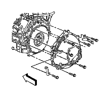
7. Install the flywheel housing to the engine block.
8. Install the flywheel housing bolts.
^ Tighten the flywheel housing bolts to 50 Nm (37 ft. lbs.).
9. Using an engine hoist and the J 41798 lower the engine onto the crossmember.
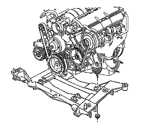
10. Install the engine mount nuts.
^ Tighten the engine mount nuts to 65 Nm (48 ft. lbs.).
11. Install the spark plugs.
12. Remove the J 41798 from the engine.
13. Install the A/C compressor bracket.
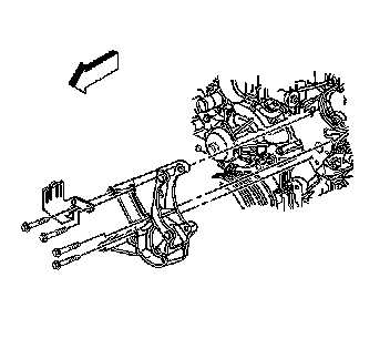
14. Install the generator bracket and power steering pump bracket.
15. Install the generator bracket bolts until snug.
16. Tighten the generator bracket bolts in the following order:
1. Inner power steering pump reservoir bracket bolt
2. Upper generator bracket bolt
3. Outer power steering pump reservoir bracket bolt
4. Lower generator bracket bolt
^ Tighten the generator bracket bolts to 50 Nm (37 ft. lbs.).
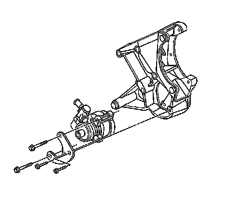
17. Install the power steering pump, with reservoir, to the generator bracket.
18. Install the power steering pump brace.
19. Install the power steering pump bolts.
^ Tighten the power steering pump bolts to 25 Nm (18 ft. lbs.).
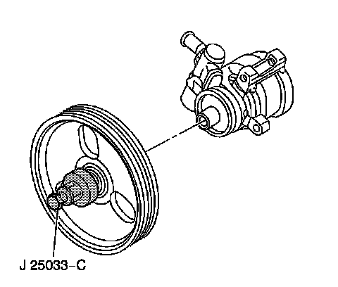
20. Using the J 25033-C install the power steering pump pulley.
21. Install the power steering pump pulley hub cap, if necessary.
22. Roll the engine and crossmember underneath the vehicle.
23. Partially lower the vehicle onto the engine and crossmember.
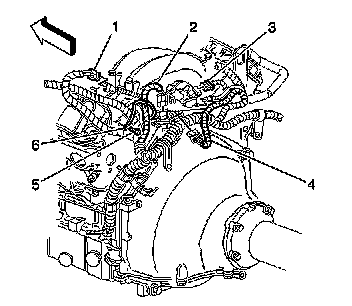
24. Install the ground strap (6) and ground strap bolt (5) to the rear of the left cylinder head.
^ Tighten the ground strap bolt (5) to 32 Nm (24 ft. lbs.).
25. Route the electrical harness and connect the following electrical connectors at the rear of the engine:
^ The engine oil pressure sensor (2)
^ The MAP sensor (3)
^ The CMP sensor (4)
26. Connect the vacuum hose to the MAP sensor.
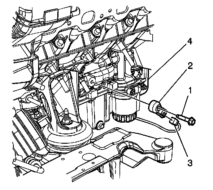
27. Reconnect the electrical connector for the knock sensor, left side.
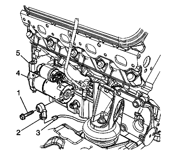
28. Reconnect the electrical connector for the knock sensor, right side.
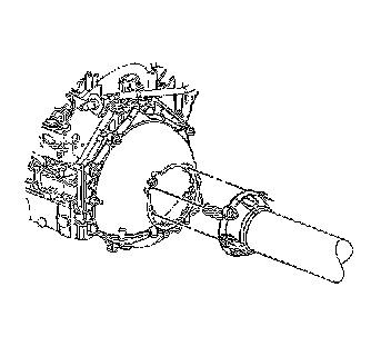
29. Slide the engine and crossmember rearward. Do not force the engine onto the propeller spline.
30. Position the engine to the proper height and angle in order to install the propeller input shaft.
31. Insert the propeller input shaft into the clutch driven plate hub while maintaining the proper angle, DO NOT force. Rotate the shaft slightly to bring the 2 splines into alignment, if necessary.
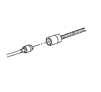
32. Slowly seat the flywheel housing to the driveline.
33. Install the driveline support bolts.
^ Tighten the driveline support bolts to 50 Nm (37 ft. lbs.).
34. Clip the clutch actuator hose to the clutch actuator hose clip.
35. Connect the master cylinder hose to the clutch actuator hose.
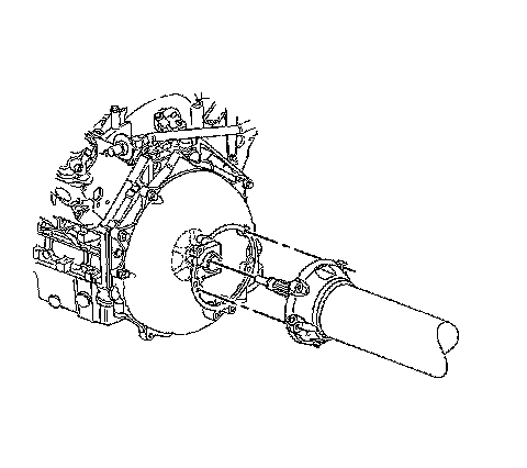
36. Important: DO NOT tighten the flywheel hub collar bolt at this time.
Install the driveline support bolts.
^ Tighten the driveline support bolts to 50 Nm (37 ft. lbs.).
37. Hand tighten the flywheel hub collar bolt.
38. Lower the vehicle onto the crossmember and align the dowels.
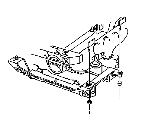
39. Important: Use only hand tools when tightening or torquing crossmember nuts.
By HAND, install new crossmember nuts until snug.
^ Tighten the crossmember nuts to 110 Nm (81 ft. lbs.).
40. Raise and suitably support the vehicle.
41. Remove the J 39580 and the J 39580-500 .
42. Remove the J 42203 from the vehicle.
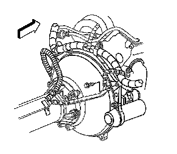
43. Route the transmission wire harness into place.
44. Install the transmission wire harness bracket bolts.
^ Tighten the transmission wire harness bracket bolts to 50 Nm (37 ft. lbs.).
45. Install the front transverse leaf spring.
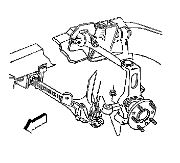
46. Install the lower control arm stud to the steering knuckle.
47. Install a NEW steering knuckle nut.
0. Tighten the steering knuckle nut to 20 Nm (15 ft. lbs.) to seat the ball joint stud.
1. Torque the steering knuckle nut an additional 210 degrees using J 36660-A .
2. Check the steering knuckle nut for a final torque of 55 Nm (41 ft. lbs.)
48. Connect the ABS electrical connector clips to the crossmember, if equipped.
49. Install the front stabilizer shaft.
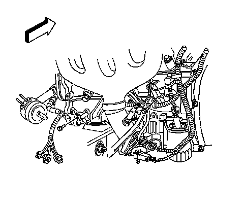
50. Clip the transmission wire harness the engine wire harness, at the white tape.
51. Install the transmission wire harness clip bolts to the engine block.
0. Tighten the transmission wire harness clip bolt, near the harness ground, to 32 Nm (23 ft. lbs.).
1. Tighten the transmission wire harness clip bolt, near the oil pan, to 25 Nm (18 ft. lbs.).
52. Install the EVO electrical connector clips to the crossmember.
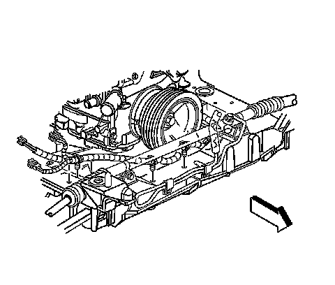
53. Clip the transmission wire harness to the crossmember.
54. If equipped with RTD connect the following electrical connectors:
^ Position sensor pigtail
^ Shock absorber damper
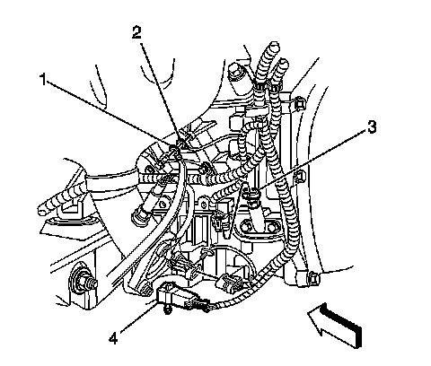
55. Position the ground straps, 1 and 2, to the engine block.
56. Install the engine ground strap bolt.
^ Tighten the engine wire harness ground bolt to 32 Nm (23 ft. lbs.).
57. Connect the left HO2S electrical connector.
58. Connect the engine oil temperature sensor (3) electrical connector.
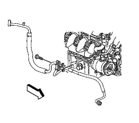
59. Install the AC compressor and condenser hose to the A/C compressor.
60. Install the A/C compressor and condenser hose bolt at the compressor.
^ Tighten the A/C compressor and condenser hose bolt, at the compressor, to 27 Nm (20 ft. lbs.).
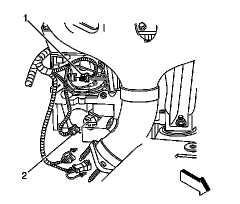
61. Connect the right front HO2S sensor electrical connector.
62. Connect the oil level sensor (2) electrical connector.
63. Connect the CKP sensor (1) electrical connector.
64. Install the starter motor.
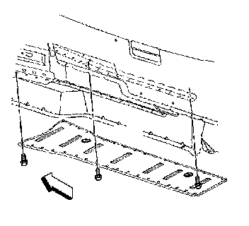
65. Install the driveline close-out panel.
66. Install the driveline close-out panel bolts.
^ Tighten the driveline close-out panel bolts to 12 Nm (106 inch lbs.).
67. Install the catalytic converter.
68. Install the front tires and wheels.
69. Lower the vehicle.
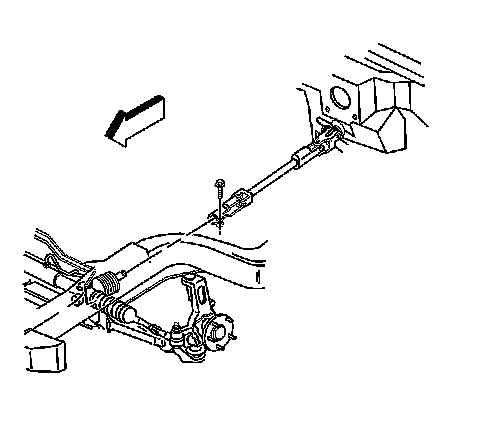
70. Install the intermediate steering shaft to the steering gear.
71. Install the intermediate steering shaft bolt.
^ Tighten the intermediate steering shaft bolt to 48 Nm (35 ft. lbs.).
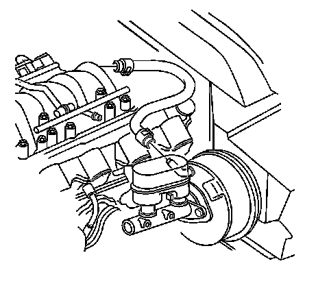
72. Install the power brake booster vacuum hose.
73. Install the generator.
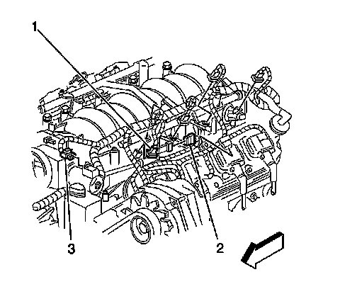
74. Connect the following electrical connectors to the engine:
^ The fuel injectors (1)
^ The ignition coil main harness connectors
^ The EVAP solenoid (2)
^ The electric throttle motor (3)
^ The TP sensor
^ The ECT sensor
^ The A/C compressor
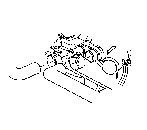
75. Install the heater hoses to the water pump.
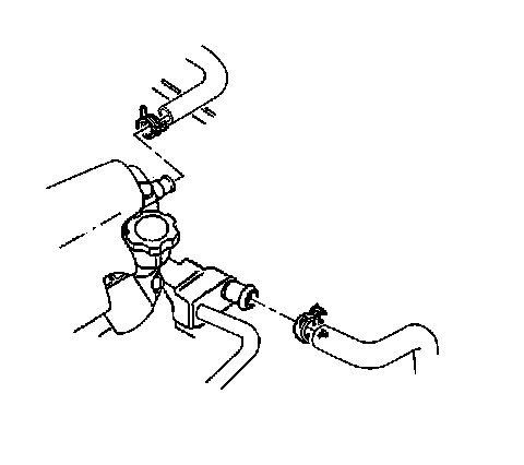
76. Install the radiator hoses to the water pump.
77. Install the fuel feed hose.
78. Connect the EVAP emission canister purge hose at the fuel line.
79. Install the accessory drive belt.
80. Install the BPMV bracket.
81. Install the radiator.
82. Recharge the A/C system. Refer to Refrigerant Recovery and Recharging .
83. Program the transmitters. Refer to Transmitter Programming (Domestic and Japan) Transmitter Programming (Export - Including Canada). Programming and Relearning
84. Bleed the clutch hydraulic system, if equipped. Refer to Hydraulic Clutch Bleeding .
85. Perform the CKP system variation learn procedure. Service and Repair
86. Disable the ignition system.
87. Crank the engine several times. Listen for any unusual noises or evidence that parts are binding.
88. Enable the ignition system.
89. Start the engine and listen for unusual noises.
90. Check the vehicle oil pressure gage and confirm that the engine has acceptable oil pressure .If necessary, install an oil pressure gage and measure the engine oil pressure.
91. Run the engine speed at about 1,000 RPM until the engine has reached normal operating temperature.
92. Listen for sticking lifters and other unusual noises.
93. Inspect for fuel, oil, and/or other coolant leaks while the engine is running.
94. Perform a final inspection for the proper engine oil and coolant levels.