Information Bus: Description and Operation
DATA LINK COMMUNICATIONS DESCRIPTION AND OPERATIONThe scan tool accesses the following data lines:
^ The Brake Pressure Control Valve (BPMV), on vehicles with antilock brake systems
^ The Powertrain Control Module (PCM)
The WHT wire at cavity 7 of the Data Link Connector (DLC) OBD 2 provides access to the BPMV and to the PCM. The RED wire at cavity 16 provides voltage to the scan tool. The WHT/BLK wire at cavity 4 and the BRN wire at cavity 5 provides ground to the scar tool.
The data lines monitor the module for diagnostic purposes and for Diagnostic Trouble Codes (DTCs).
IMPORTANT: Do not use a scan tool that displays faulty data. Report the scan tool problem to the manufacturer. Use of a faulty scan tool can result in misdiagnosis and unnecessary parts replacement.
Data Link Connector (DLC):
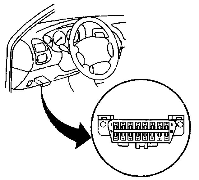
The provision for communicating with the control module is the Data Link Connector (DLC). The DLC is located under the instrument panel to the left of the steering column. The DLC is used to connect to a scan tool. Some common uses of the scan tool are listed below:
^ Identifying stored Diagnostic Trouble Codes (DTCs)
^ Clearing the DTCs
^ Performing output control tests
^ Reading the serial data