Fuel Injection Operation
The PCM controls the amount of fuel the fuel injector supplies to each cylinder by controlling the ON time, or length of pulse, of each individual injector. The delivery timing of the fuel into the cylinder head intake port by the fuel injector is controlled by the PCM. The timing and pulse of the fuel injectors is carefully calculated with inputs from the various sensors so that a suitable air/fuel mixture is supplied to the engine for every driving condition. There are two types of injection timing. One is synchronous injection, when fuel injection is synchronous with the ignition signal or the signal from the Camshaft Position (CMP) sensor. The other is asynchronous injection, when fuel injection takes place independently of the ignition signal or the signal from the CMP sensor.The PCM first calculates the correct timing of the fuel injectors by factoring the engine speed and the air volume together. Then the PCM applies certain compensations that are based on the information provided by various sensors which detect the state of the engine and the current driving conditions.
Synchronous Injection
When starting the engine, the fuel injectors inject the fuel simultaneously and synchronously at every camshaft position (CMP) sensor signal. When the engine is starting at a cold state, the amount of fuel is determined by the Engine Coolant Temperature (ECT) sensor and is divided and injected.
Once the engine is running, the fuel injection occurs in a cylinder only when the cylinder is in the exhaust stroke. The PCM detects the compression stroke of cylinder 1 through the CMP sensor signal.
Asynchronous Injection
Whenever a change in the throttle valve opening exceeds a specified value, as determined by the PCM, additional fuel is injected simultaneously into the cylinders which are in the intake and exhaust strokes. This is in addition to the above synchronous injection and is not based on the ignition signal.
Engine Starting Enrichment
In order to improve starting performance, fuel enrichment during start up is carried out. For a certain time after the engine is started, the air/fuel mixture is enriched slightly in order to stabilize the engine speed. The amount of compensation varies depending on the engine coolant temperature as measured by the ECT sensor.
Engine Warm-Up Enrichment
When the engine is cold, additional fuel is added in order to ensure good driveability. The level of enrichment of the air/fuel mixture is gradually decreased until the Engine Coolant Temperature (ECT) sensor reaches a specified value.
Acceleration Enrichment
During acceleration, the pulse of the fuel injectors is lengthened in order to deliver more fuel. The additional fuel required is relative to the engine coolant temperature. Acceleration Enrichment ensures smooth and reliable engine acceleration.
Power Enrichment
In order to provide maximum power during high engine load driving conditions, the air/fuel mixture is enriched when the throttle valve opening is more than a specified, PCM determined, value.
System Voltage Compensation
A power supply system voltage drop will delay the mechanical operation of the fuel injector. The actual injector ON time becomes shorter when the system voltage decreases. In order to compensate for this, the fuel injector pulse width signal is lengthened.
Crank Signal
The crank signal is sent from the starter motor circuit. When the starter motor circuit is energized as the ignition switch is in the START position, a crank signal is supplied to the PCM. The PCM increases the fuel injector pulse when receiving a voltage on the crank signal circuit. The slight increase in fuel provides quicker and smoother engine start-up. The crank signal is also used as an input for running certain engine control system diagnostics, such as the CKP sensor DTC P0335. The crank signal input can be monitored on a scan tool as the Starter Switch parameter.
Base Air/Fuel Ratio Compensation
The base air/fuel ratio may vary due to differences in individual engines and mileage. In order to compensate for such variations, feedback information is used to adjust the base air/fuel mixture to maintain the optimum air/fuel ratio.
Fuel Cutoff
Fuel injection stops when decelerating (i.e., when the throttle valve is at idle position and the engine speed is high), so that unburned gas will not be exhausted. Fuel injection starts again when the above conditions are no longer present.
Fuel delivery also stops when the engine speed exceeds 6,800 RPM. This will prevent engine overrun which adversely affects the engine. Fuel delivery starts again when the engine speed decreases to less than 6,500 RPM.
Air/Fuel Ratio Feedback Compensation (Closed Loop Operation)
In order to obtain efficient performance of the 3-way Catalytic Converter (TWC) and a high clarification rate of CO, HC and NOx in the exhaust gas stream, the air/fuel mixture must be kept as close to the theoretical air/fuel ratio of 14.7:1 as possible. In order to accomplish this the PCM first compares the input voltage from the Heated Oxygen Sensor 1 (HO2S 1) with a specified reference voltage. If the HO2S 1 input voltage is higher than the specified reference voltage, the PCM determines that the air/fuel ratio is richer than the theoretical air/fuel ratio and reduces the fuel. If the input voltage from the HO2S 1 is lower than the specified reference voltage, the PCM determines that the air/fuel ratio is leaner and increases the fuel. By repeating these operations, the PCM can adjust the air/fuel ratio in order to be closer to the theoretical air/fuel ratio. Control of the fuel delivery system as just described is known as Closed Loop operation.
Closed Loop Fuel Control Operation
Closed Loop Fuel Control Operation:
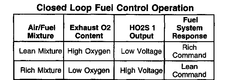
The Closed Loop fuel control operation will not take place under any of the following conditions:
^ At engine start up
^ When the fuel injection is increased just after engine start up.
^ When the Engine Coolant Temperature (ECT) sensor is indicating a low coolant temperature.
^ When the engine is operating under a high demand, such as at Wide Open Throttle (WOT).
^ At fuel cut-off
^ When the HO2S 1 is cold - Open Loop operation.
Control of the air supply that is mixed with the metered fuel is detailed in the description of the air intake system. Refer to Air Intake System Description.