Transmission Support Replacement
Transmission Support Replacement
Tools Required
J 28467-360 Engine Support Fixture
Removal Procedure
1. Install the J 28467-360 . Refer to Engine Support Fixture in Engine Mechanical.
2. Raise and suitably support the vehicle. Refer to Lifting and Jacking the Vehicle in General Information.
3. Remove the front tire and wheel assemblies. Refer to Tire and Wheel Removal and Installation in Tires and Wheels.
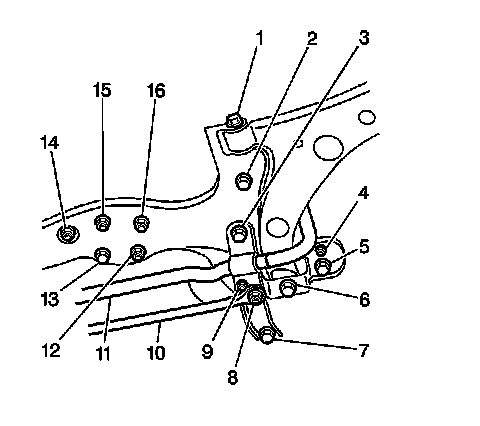
4. Remove the following components from the crossmember:
* The bolt (13)
* The 4 nuts (12, 14, 15, 16)
5. Support the front suspension crossmember with a jack.
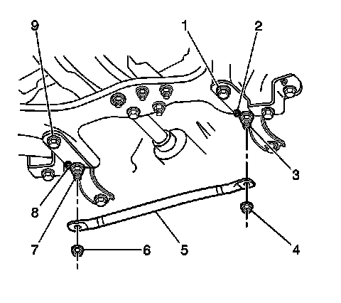
6. Remove the following components:
* The 2 suspension support brace nuts (4, 6)
* The suspension support brace (5)
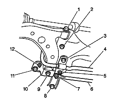
7. Remove the following from the right side of the vehicle:
* The 6 bolts (2, 3, 8, 9, 11)
* The stud (7)
8. Remove the following components from the left side of the vehicle:
* The 6 bolts (2, 3, 5, 6, 7)
* The stud (8)
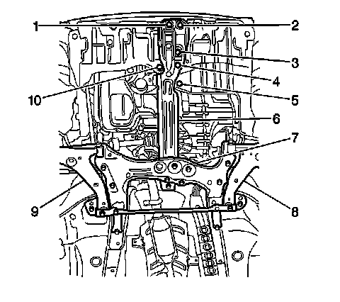
9. Remove the 2 bolts (5, 10) which secure the 2 engine splash shields to the transaxle support (6).
10. Remove the 2 bolts (3, 4) which secure the front transaxle mount to the transaxle support.
11. Remove the 2 bolts (1, 2) which secure the trans support to the vehicle.
12. Lower the jack supporting the front suspension crossmember until the rear transaxle support mounting studs have cleared the crossmember.
13. Remove the transaxle support (6) from the front suspension crossmember (7).
Installation Procedure
1. Install the transaxle support (6) to the front suspension crossmember (7).
2. Raise and support the front suspension crossmember (7), the trans support (6), the 2 control arms (8, 9), and the stabilizer shaft (if equipped) together as a unit with a jack.
3. Secure the transaxle support to the vehicle with 2 bolts (1, 2). Do not torque the bolts.
Notice: Refer to Fastener Notice in Cautions and Notices.
4. Install the 2 bolts (3, 4) which secure the front transaxle mount to the transaxle support.
Tighten the front transaxle mount bolts to 64 N.m (47 lb ft).
5. Install the engine splash shield bolts (5, 10) which secure the 2 engine splash shields to the transaxle support.
Tighten the engine splash shield bolts to 10 N.m (89 lb in).
6. Install the 2 studs (3, 7).
Tighten the 2 stabilizer shaft mounting bracket studs to 147 N.m (109 lb ft).
7. Install, but do not tighten, the 6 bolts (2, 3, 5, 6, 7) on the left side of the vehicle.
8. Install, but do not tighten, the 6 bolts (2, 3, 8, 9, 11) on the right side of the vehicle.
9. Remove the jack from the center of the crossmember.
10. Install the nut (14) and the bolt (13).
Tighten the engine crossmember to suspension crossmember nut and the bolt to 60 N.m (45 lb ft).
11. Install the 3 nuts (12, 15, 16).
Tighten the front suspension crossmember nuts to 57 N.m (42 lb ft).
12. Install the following components to the vehicle:
* The suspension support brace (5)
* The 2 suspension support brace nuts (4, 6)
Tighten the suspension support brace nuts to 69 N.m (51 lb ft).
13. Install the tire and wheel assemblies. Refer to Tire and Wheel Removal and Installation in Tires and Wheels.
14. Lower the vehicle.
15. Raise the vehicle on a drive-on lift or move the vehicle to an alignment rack. The weight of the vehicle must be supported by the vehicle's tires and wheels. Refer to Lifting and Jacking the Vehicle in General Information.
16. Stabilize the suspension by lifting up and pushing down the front bumper.
17. Torque the 2 bolts (1, 2).
Tighten the 2 transaxle support mounting bolts to 60 N.m (45 lb ft).
18. Torque the bolt (6).
Tighten the right control arm retaining bracket inner bolt to 175 N.m (129 lb ft).
19. Torque the 2 bolts (2, 3).
Tighten the 2 crossmember front outer bolts to 225 N.m (167 lb ft).
20. Torque the 2 bolts (5, 7).
Tighten the right control arm retaining bracket outer bolt and the right control arm retaining bracket rear bolt to 147 N.m (109 lb ft).
21. Torque the bolt (9).
Tighten the left control arm retaining bracket inner bolt to 175 N.m (129 lb ft).
22. Torque the 2 bolts (2, 3).
Tighten the 2 crossmember front outer bolts to 225 N.m (167 lb ft).
23. Torque the 2 bolts (8, 11).
Tighten the left control arm retaining bracket outer bolt and the left control arm retaining bracket rear bolt to 147 N.m (109 lb ft).
24. Lower the vehicle.
25. Remove the J 28467-360 . Refer to Engine Support Fixture in Engine Mechanical.
26. Inspect the front wheel alignment. Refer to Wheel Alignment Measurement in Wheel Alignment.