Malfunction Indicator Lamp (MIL) Always On
Diagnostic Chart:
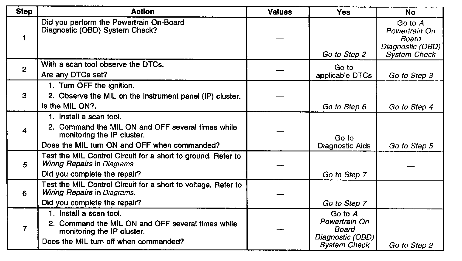
SYSTEM DESCRIPTION
The Powertrain On-Board Diagnostic (OBD) System Check must be the starting point for any driveability complaint diagnosis. Perform a careful visual and physical inspection of the Powertrain Control Module (PCM) and engine grounds for being clean and tight. Refer to Visual and Physical Check in Symptoms. A Powertrain On Board Diagnostic (OBD) System Check is an organized approach to identifying a problem created by an electronic engine control system malfunction. Initial Inspection and Diagnostic Overview
The Powertrain Control Module (PCM) controls the Malfunction Indicator Lamp (MIL) by providing a ground path through the MIL control circuit to turn ON the MIL. When the ignition is turned ON, the MIL will remain on until the engine is running, if no Diagnostic Trouble Codes (DTC) are stored. If the MIL is illuminated, then the engine stalls, the MIL will remain illuminated so long as the ignition is ON.
DIAGNOSTIC AIDS
Inspect for the following conditions:
IMPORTANT: Remove any debris from the connector surfaces before servicing a component. Inspect the connector gaskets when diagnosing or replacing a component. Ensure that the gaskets are installed correctly. The gaskets prevent contaminate intrusion.
^ Poor terminal connection - Inspect the harness connectors for backed out terminals, improper mating, broken locks, improperly formed or damaged terminals, and faulty terminal to wire connection. Use a corresponding mating terminal to test for proper tension.
^ Damaged harness - Inspect the wiring harness for damage. If the harness inspection does not reveal a problem, observe the display on the scan tool while moving connectors and wiring harnesses related to the sensor. A change in the scan tool display may indicate the location of the fault.
^ PCM and engine grounds for clean and secure connections
If the DTC is determined to be intermittent, reviewing the Failure Records can be useful in determining when the DTC was last set.
Malfunction Indicator Lamp (MIL) On Steady
The numbers below refer to the step numbers on the diagnostic table:
5. Using a test lamp connected to battery positive voltage, probe the MIL control circuit at the PCM.