Rear Suspension
Removal Procedure- Tools Required
- J 21474-18 3/8 Inch Nut
- J 21474-193/8 Inch Bolt
- J 29376-A Rear Control Arm Bushing Service Set
- J 29376-95 Rear Control Arm Bushing Adapter
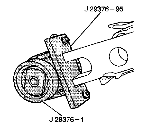
1. Raise and support the vehicle. Refer to Vehicle Lifting.
2. Remove the tire and wheel assemblies. Refer to Tire and Wheel Removal and Installation.
3. Disconnect the brake hoses from the axle. Refer to Brake Hose Replacement - Rear in Brakes and Traction Control.
4. Remove the wheel speed sensor harness from the retainers on the axle. Refer to Wheel Speed Sensor Jumper Harness Replacement - Rear in Brakes and Traction Control.
5. Remove the following components from the control arm:
- The bolts
- The washers
- The nuts
6. Rotate the control arm downward in order to gain access to the bushings.
7. Install the J 29376-95 on the rear control arm.
8. Install the coupling from the J 29376-A to the J 29376-95 on the rear control arm.
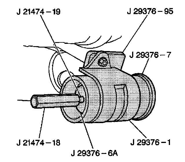
9. Assemble the following bushing removal tools as shown:
9.1. J 21474-19
9.2. The remover from the J 29376-A
9.3. The pressure plate from the J 29376-A
9.4. J 21474-18
10. Tighten the J 21474-19 until the bushing is removed from the control arm. Disassemble the bushing removal tools.
Installation Procedure
1. Coat the outside case of the bushing with a light coat of grease prior to installation.
2. Insert the bushing into the control arm.
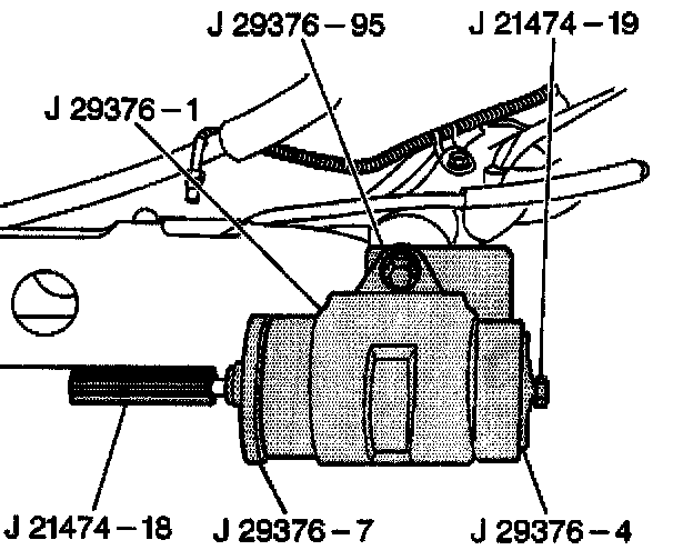
3. Assemble following bushing installation tools as shown:
3.1. J 21474-19
3.2. The pressure plate from the J 29376-A
3.3. The installer from the J 29376-A
3.4. J 21474-18
4. Tighten the J21474-19 until the bushing is completely seated in the control arm.
5. Disassemble the bushing installation tools.
6. Install the following components:
- The bolts
- The nuts
- The washers
7. Hand tighten the nuts.
8. Install the wheel speed sensor harness to the rear axle. Refer to Wheel Speed Sensor Jumper Harness Replacement - Rear in Brakes and Traction Control.
9. Connect the brake hoses to the rear axle. Refer to Brake Hose Replacement - Rear in Brakes and Traction Control.
10. Install the tire and wheel assemblies. Refer to Tire and Wheel Removal and Installation.
11. Lower the vehicle.
Notice: Refer to Fastener Notice in Service Precautions.
12. Tighten the control arm nuts.
- Tighten the control arm nuts to 120 Nm (52 ft. lbs.).