Intake Manifold Replacement - Lower
Removal ProcedureImportant: The two bolts which fasten the lower intake manifold to the cylinder head are accessible only after the upper intake is removed. The bolts are located in the right front and left rear corners of the lower intake manifold. Remove the upper intake manifold to service the lower intake.
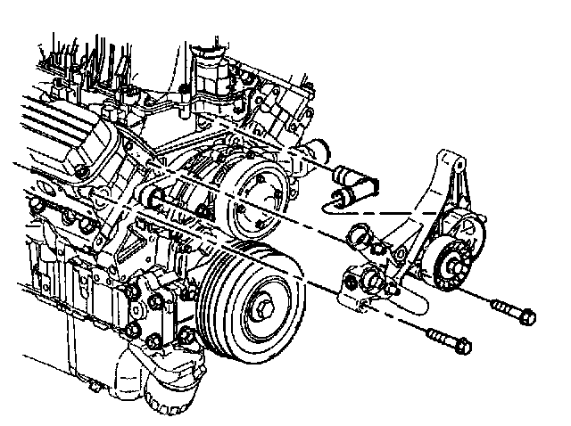
1. Remove the upper intake manifold. Refer to Intake Manifold Replacement (Upper).
2. Remove the generator braces.
3. Remove the generator.
4. Remove the drive belt tensioner with mounting bracket and the heater water bypass inlet pipe. Refer to Drive Belt Tensioner Replacement.
5. Remove the EGR tube from the lower intake manifold.
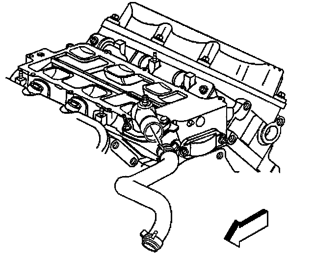
6. Remove the radiator inlet hose from the water outlet housing. Refer to Radiator Hose Replacement - Inlet in Cooling System.
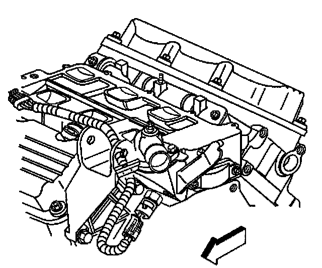
7. Disconnect the Engine Coolant Temperature (ECT) sensor wiring harness connector.
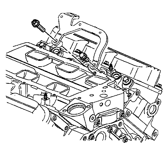
8. Remove the generator brace bracket bolts.
9. Remove the generator brace bracket.
10. Remove the evaporative emissions canister purge solenoid valve. Refer to EVAP Canister Purge Valve Replacement in Powertrain Management.
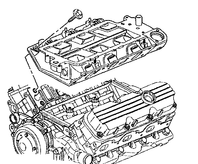
11. Remove the lower intake manifold bolts. Remove the lower intake manifold.
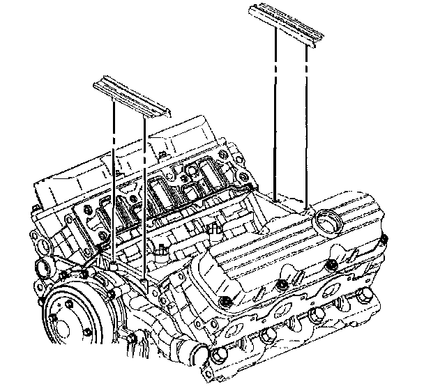
12. Remove the lower intake manifold seals.
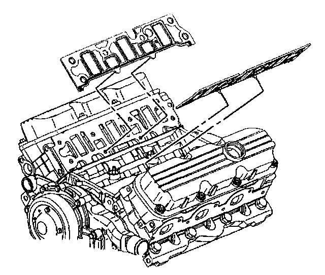
13. Remove the lower intake manifold gaskets.
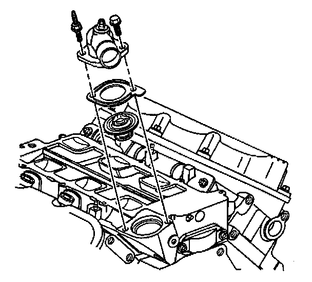
14. If replacing the lower intake manifold, remove the water outlet housing bolts, the water outlet housing, the gasket and the thermostat. Refer to Thermostat Replacement in Cooling System.
15. If replacing the lower intake manifold, remove the Engine Coolant Temperature (ECT) sensor. Refer to ECT Sensor Replacement in Powertrain Management.
16. Inspect the flatness of the inlet flanges.
17. Clean the engine block.
18. Clean the cylinder block, heads, and the intake manifold sealing surface with a suitable solvent.
19. Clean the intake manifold bolts and bolt holes of adhesive compound.
Installation Procedure
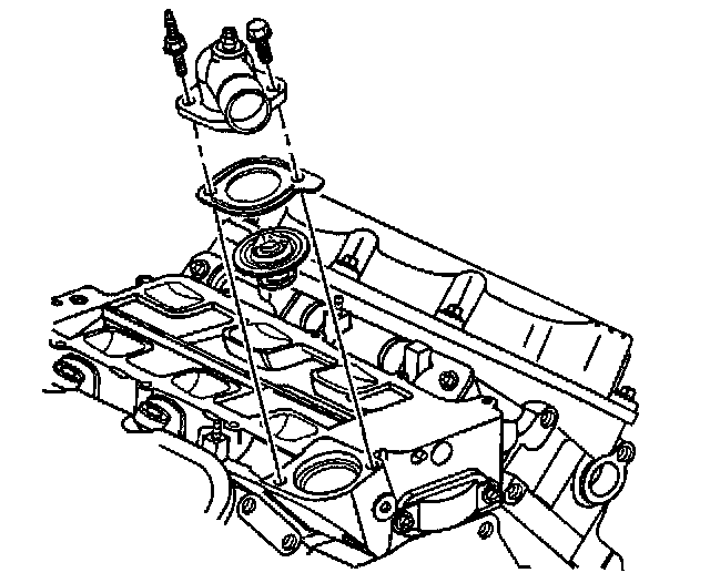
1. If replacing the lower intake manifold, install the Engine Coolant Temperature (ECT) sensor. Refer to ECT Sensor Replacement in Powertrain Management.
2. If replacing the lower intake manifold, install the thermostat, the gasket, and the water outlet housing. Refer to Thermostat Replacement in Cooling System.
Notice: Refer to Fastener Notice in Service Precautions.
3. Install the water outlet housing bolts.
- Tighten the water outlet housing bolts to 27 Nm (20 ft. lbs.).
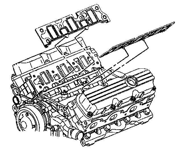
4. Install the lower intake manifold gaskets.
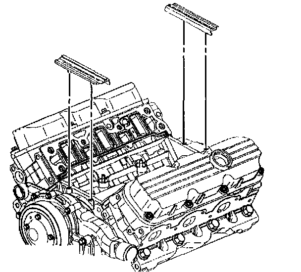
5. Apply sealer GM P/N 12345336 or equivalent to the ends of the intake manifold seals.
6. Install the lower intake manifold seals.
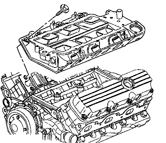
7. Install the lower intake manifold.
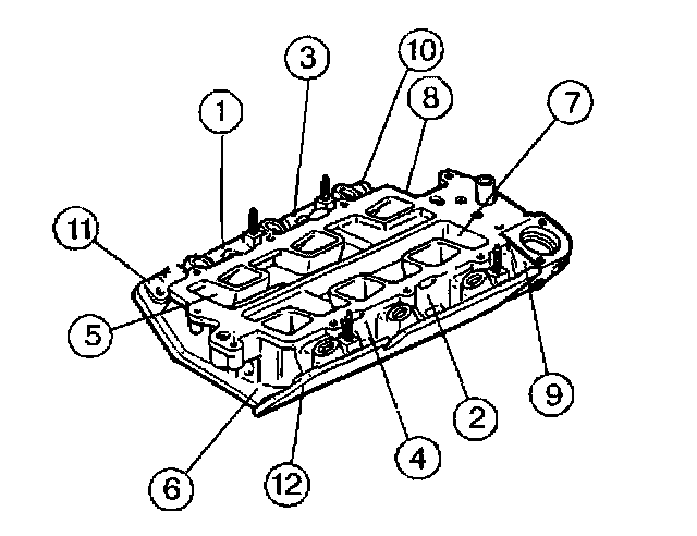
8. Install the lower intake manifold bolts (1 - 12). Apply thread lock compound GM P/N 12345382 or equivalent to the two hidden bolts (5 and 7) and make sure they are installed.
- Tighten the lower intake manifold bolts (1 - 12) in sequence to 15 Nm (11 ft. lbs.).
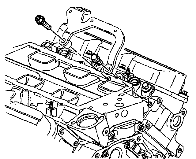
9. Install the generator brace bracket.
10. Install the generator brace bracket bolts.
- Tighten the generator brace bracket bolts to 50 Nm (37 ft. lbs.).
11. Install the evaporative emissions canister purge solenoid valve.
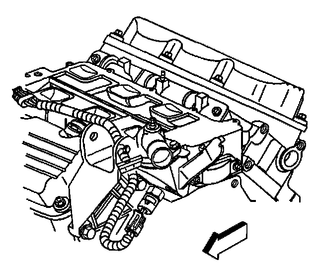
12. Connect the engine coolant temperature (ECT) sensor wiring harness connector.
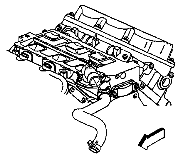
13. Install the radiator inlet hose to the water outlet housing. Refer to Radiator Hose Replacement -Inlet in Cooling System.
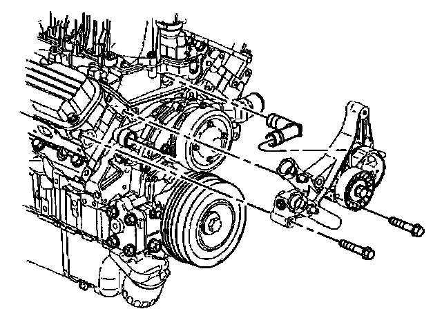
14. Install the drive belt tensioner mounting bracket and the water heater bypass inlet pipe. Refer to Drive Belt Tensioner Replacement.
15. Install the EGR tube to the lower intake manifold.
- Tighten the EGR tube bolt to 29 Nm (21 ft. lbs.).
16. Install the generator.
17. Install the generator braces.
18. Install the upper intake manifold. Refer to Intake Manifold Replacement (Upper).