(Front)
Removal Procedure^ Tools Required
^ J 28467-B Universal Engine Support Fixture
^ J 38185 Spring Hose Clamp Pliers
^ J 41803 Engine Support Fixture
1. Position the front wheels straight ahead, then remove the ignition key to lock the steering column.
Caution: Refer to Battery Disconnect Caution in Service Precautions.
2. Disconnect the negative battery cable.
3. Raise and suitably support the vehicle. Refer to Vehicle Lifting.
4. Have a drain pan ready to catch fluid.
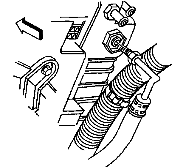
5. If equipped with the flared fitting design, disconnect the transmission oil cooler (TOC) front upper pipe fitting from the radiator, then cap the pipe fitting and plug the TOC fitting to prevent contamination.
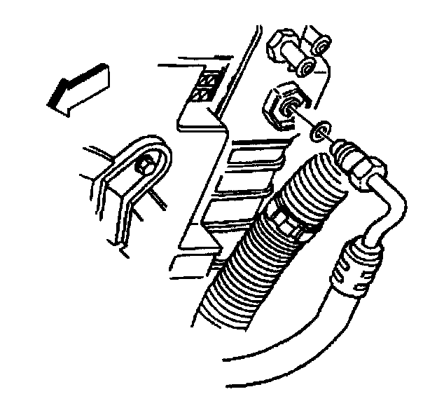
6. If equipped with the sealing washer design, disconnect the transmission oil cooler (TOC) front upper pipe fitting from the radiator, discard the sealing washer, then cap the pipe fitting and plug the TOC fitting to prevent contamination.
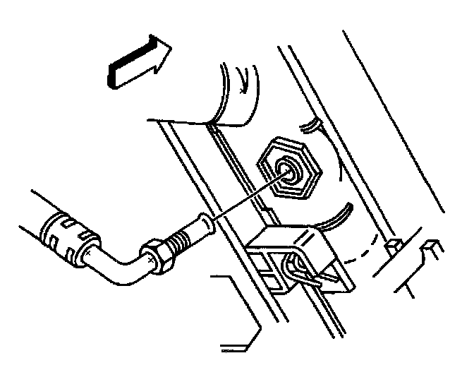
7. If equipped with the flared fitting design, disconnect the TOC front lower pipe fitting from the radiator, allow any excess fluid to drain, then cap the pipe fitting and plug the TOC fitting to prevent contamination.
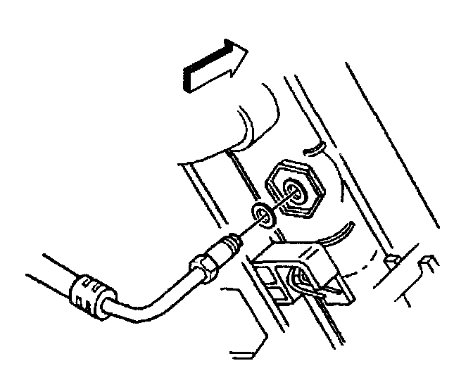
8. If equipped with the sealing washer design, disconnect the TOC front lower pipe fitting from the radiator, discard the sealing washer, allow any excess fluid to drain, then cap the pipe fitting and plug the TOC fitting to prevent contamination.
9. Drain the engine cooling system. Refer to Draining and Filling Cooling System in Cooling System.
10. Lower the vehicle; leave the vehicle on the hoist.
11. Recover the A/C system refrigerant.
12. Remove the air cleaner assembly. Refer to Air Cleaner Assembly Replacement in Powertrain Management.
13. Remove the upper and lower radiator support. Refer to Radiator Support Replacement in Cooling System.
14. Disconnect the evaporator tube - front from the condenser. Refer to Evaporator Tube Replacement (Front) in Heating and Air Conditioning.
15. Disconnect the compressor hose from the condenser. Refer to Compressor Hose Assembly Replacement in Heating and Air Conditioning.
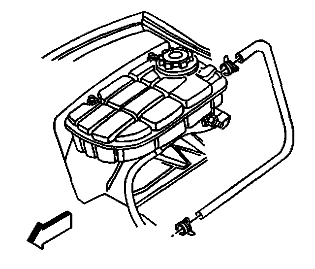
16. Using the J38185, release and reposition the coolant surge tank upper hose clamp away from the radiator inlet.
17. Separate the surge tank upper hose from the radiator inlet.
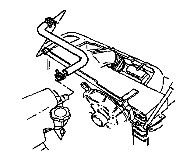
18. Using the J38185, release and reposition the radiator inlet hose clamp away from the radiator inlet.
19. Separate the radiator inlet hose from the radiator inlet.
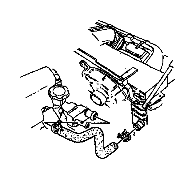
20. Using the J 38185, release and reposition the radiator outlet hose clamp away from the radiator outlet.
21. Separate the radiator outlet hose from the radiator outlet.
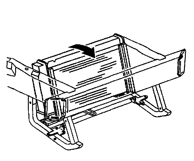
22. Carefully pivot the A/C condenser with the radiator forward and tie off to support the assembly.
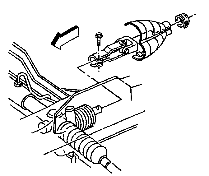
23. Remove the steering column intermediate shaft lower coupling shield.
24. Match-mark the intermediate shaft lower coupling to the power steering (P/S) gear to ensure correct orientation upon installation.
25. Remove the intermediate shaft lower coupling bolt.
26. Disconnect the intermediate shaft lower coupling from the P/S gear. Slide the intermediate shaft lower coupling off of the P/S gear steering shaft.
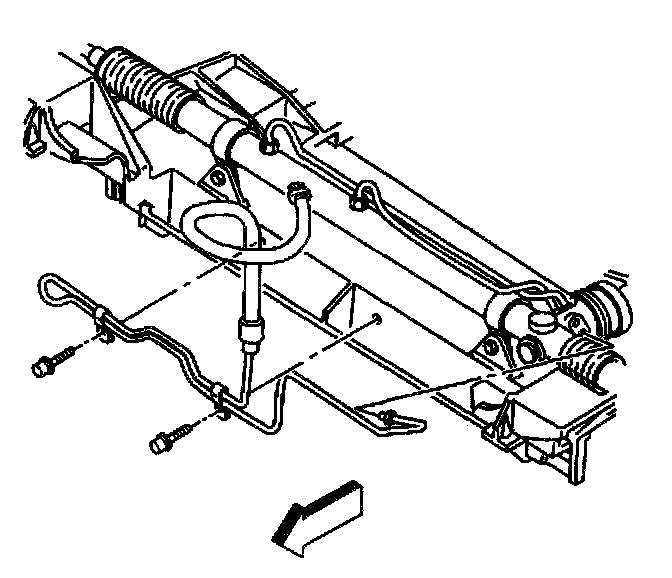
27. Remove the P/S cooler retaining bolts.
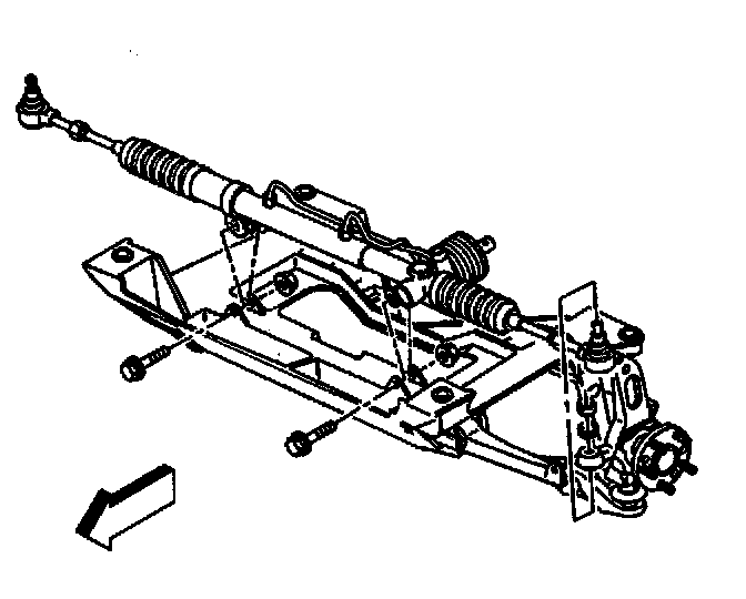
28. Remove the brake pressure modulator valve bracket. Refer to Brake Pressure Modulator Valve Bracket Replacement in Brakes and Traction Control.
29. Remove the P/S gear mounting bolts and nuts.
30. Release the P/S gear and cooler from the front suspension crossmember, then slave the gear and cooler forward.
31. Remove the A/C compressor bracket. Refer to Compressor Mounting Bracket Replacement in Heating and Air Conditioning.
32. Remove the generator from the accessory mounting bracket. Refer to Generator Replacement in Starting and Charging.
33. Install and support the engine with the J41803 and the J 28467-B.
34. Remove the RH engine mount (with bracket). Refer to Engine Mount Replacement in Engine.
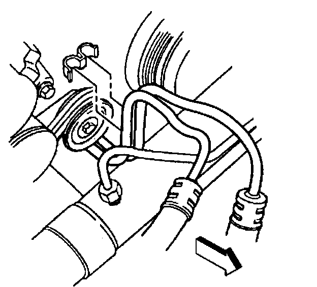
35. Remove the TOC front pipe front clip.
36. Raise the vehicle.
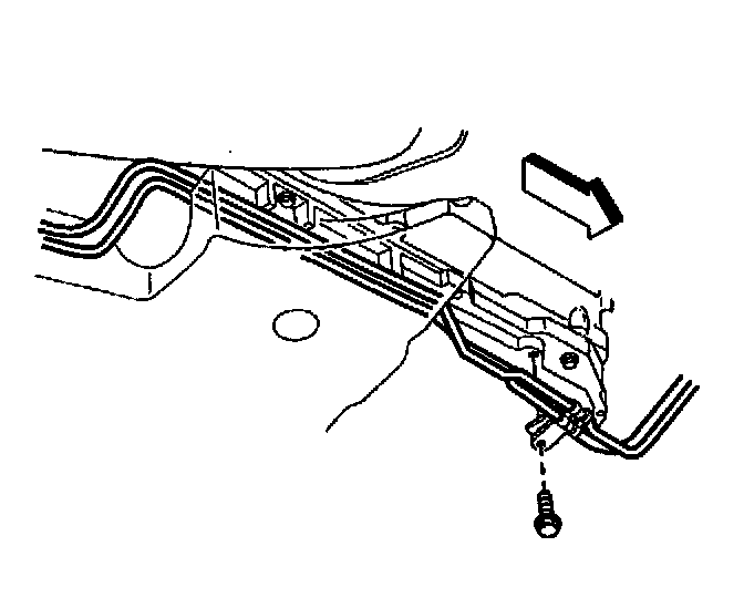
37. Remove the TOO front pipe front retaining clamp bolt and retaining clamp.
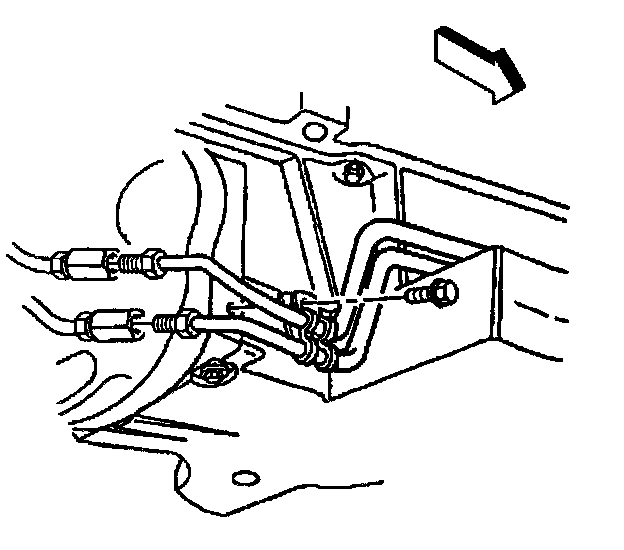
38. Remove the TOC front pipe rear retaining clamp bolt and retaining clamp.
39. Disconnect the TOC front pipe fittings from the junction fittings at the engine flywheel housing, then cap the pipe fittings and plug the junction fittings to prevent contamination.
40. Lower the vehicle; leave the vehicle slightly above the ground.
41. Finesse the TOC front pipes out of the vehicle (through the top).
Installation Procedure
^ Tools Required
^ J 28467-B Universal Engine Support Fixture
^ J 38185 Spring Hose Clamp Pliers
^ J 41803 Engine Support Fixture
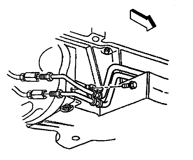
1. Install the transmission oil cooler (TOC) front pipes to the vehicle (through the top of the vehicle). Finesse the pipes into position.
2. Raise the vehicle.
3. Remove the caps from the rear of the TOC front pipes and remove the plugs from the junction fittings at the engine flywheel housing.
Notice: Refer to Fastener Notice in Service Precautions.
4. ALIGN and HAND-START, then tighten ONLY by hand to seat the TOC front upper and lower pipe fittings to the junction fittings at the engine flywheel housing.
^ Tighten the transmission oil cooler front upper and lower pipe fittings to the junction at the engine flywheel housing to 27 Nm (20 ft. lbs.).
5. Install the TOC front pipe rear retaining clamp and bolt.
^ Tighten the transmission oil cooler front pipe rear retaining clamp bolt to 2.2 Nm (19 inch lbs.).
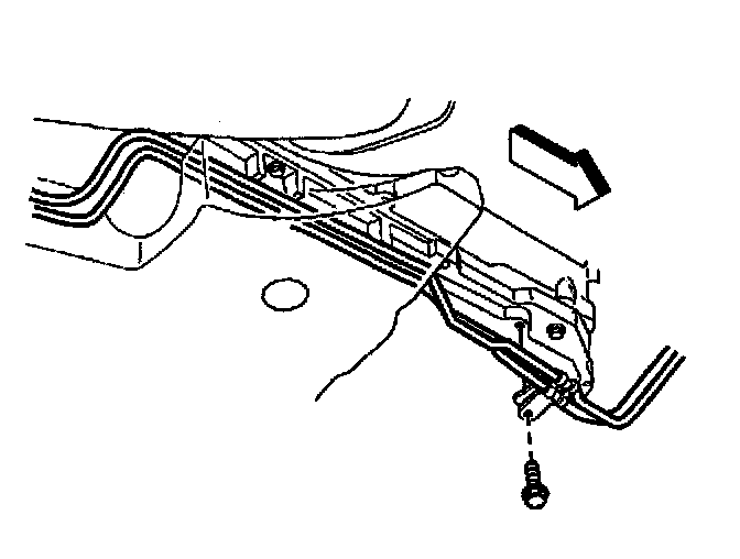
6. Install the TOC front pipe front retaining clamp and bolt.
^ Tighten the transmission oil cooler front pipe front retaining clamp bolt to 12 Nm (106 inch lbs.).
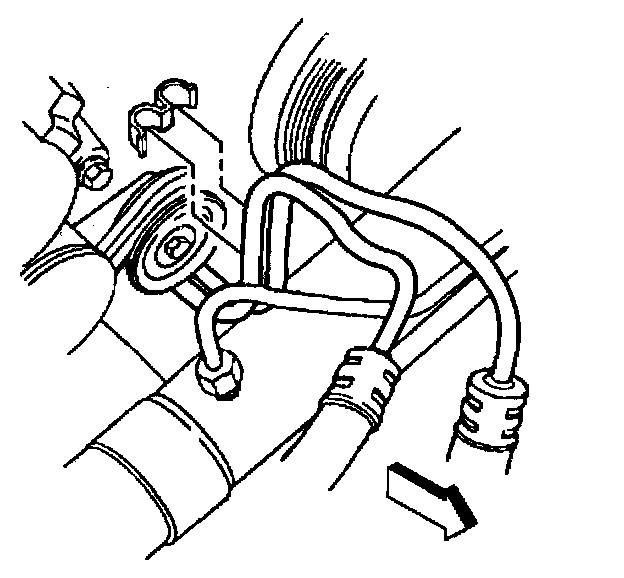
7. Lower the vehicle; leave the vehicle slightly above the ground.
8. Install the TOC front pipe front clip.
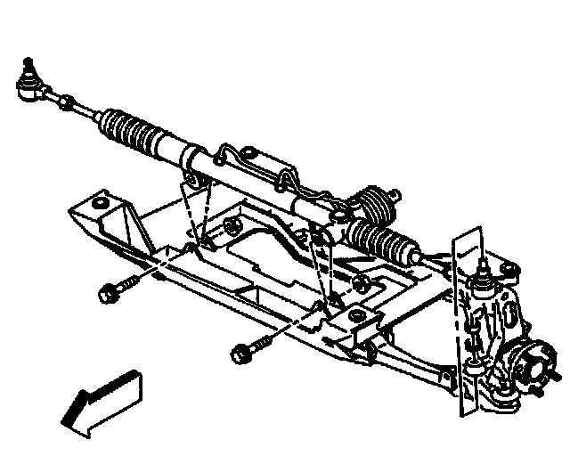
9. Install the RH engine mount (with bracket). Refer to Engine Mount Replacement in Engine.
10. Remove the J 41803 and the J 28467-B.
11. Install the generator to the accessory mounting bracket. Refer to Generator Replacement in Starting and Charging.
12. Install the A/C compressor bracket. Refer to Compressor Mounting Bracket Replacement in Heating and Air Conditioning.
13. Position the power steering (PUS) gear and cooler to the front suspension crossmember.
14. Install the brake pressure modulator valve bracket. Refer to Brake Pressure Modulator Valve Bracket Replacement in Brakes and Traction Control.
15. Install the P/S gear mounting bolts and nuts.
^ Tighten the power steering gear mounting nuts to 100 Nm (74 ft. lbs.).
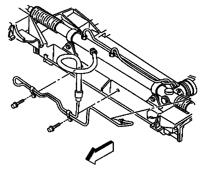
16. Install the P/S cooler retaining bolts.
^ Tighten the power steering cooler retaining bolts to 11 Nm (97 inch lbs.).
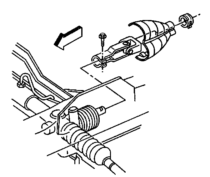
17. Connect the intermediate shaft lower coupling to the P/S gear, be sure that the intermediate shaft and the P/S gear steering shaft are orientated as marked prior to disconnecting them. Slide the intermediate shaft lower coupling onto the P/S gear steering shaft.
18. Install the intermediate shaft lower coupling bolt.
^ Tighten the steering column intermediate shaft lower coupling bolt to 34 Nm (25 ft. lbs.).
19. Install the intermediate shaft lower coupling shield.
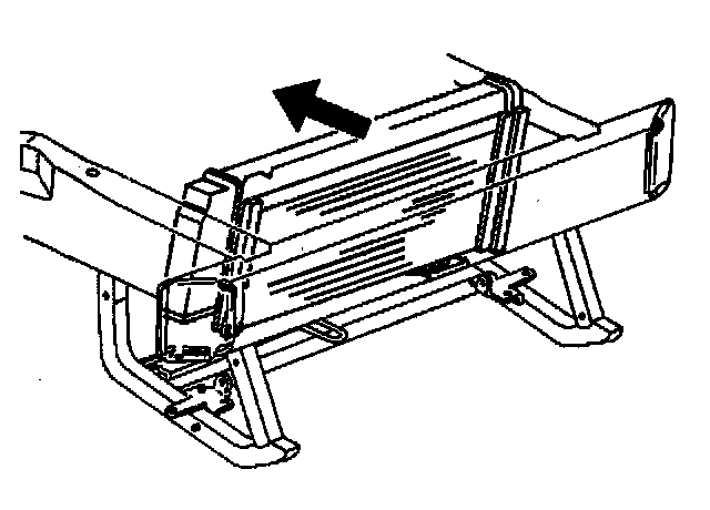
20. Remove the tie-off retainer and carefully pivot the A1C condenser and the radiator back into position.
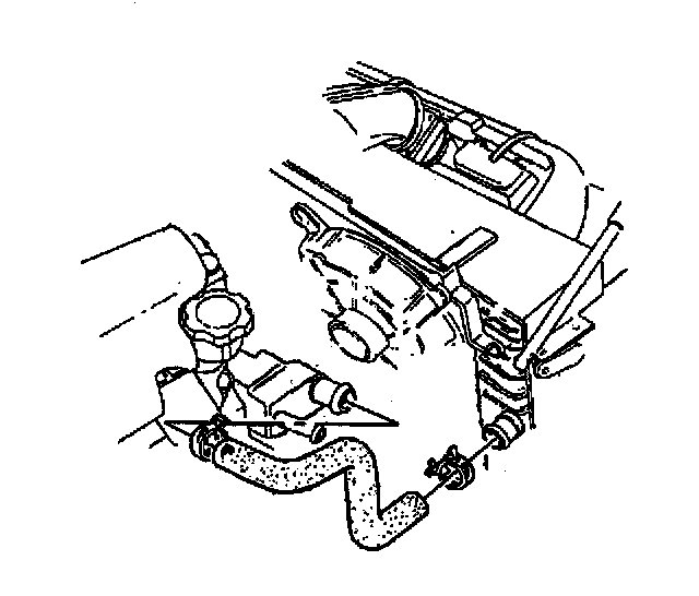
21. Install the radiator outlet hose to the radiator outlet.
22. Using the J38185, position the radiator outlet hose clamp onto the radiator outlet.
23. Install the radiator inlet hose to the radiator inlet.
24. Using the J 38185, position the radiator inlet hose clamp onto the radiator inlet.
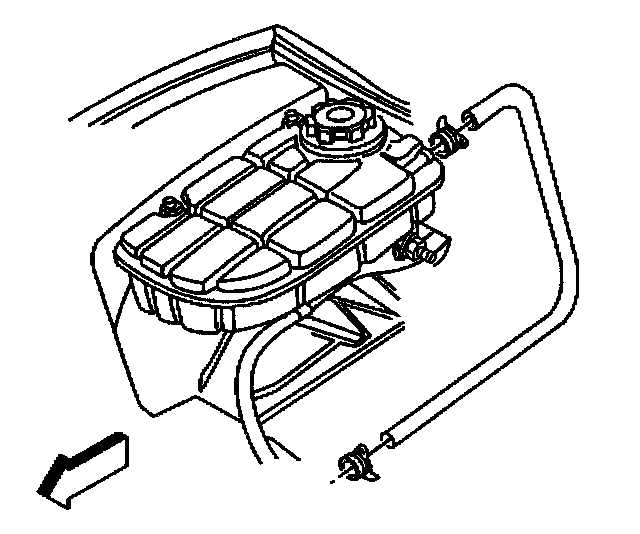
25. Install the surge tank upper hose to the radiator inlet.
26. Using the J 38185, position the coolant surge tank upper hose clamp onto the radiator inlet.
27. Connect the compressor hose to the condenser. Refer to Compressor Hose Assembly Replacement in Heating and Air Conditioning.
28. Connect the evaporator tube - front to the condenser. Refer to Evaporator Tube Replacement (Front) in Heating and Air Conditioning.
29. Install the upper and lower radiator support. Refer to Radiator Support Replacement in Cooling System.
30. Install the air cleaner assembly. Refer to Air Cleaner Assembly Replacement in Powertrain Management.
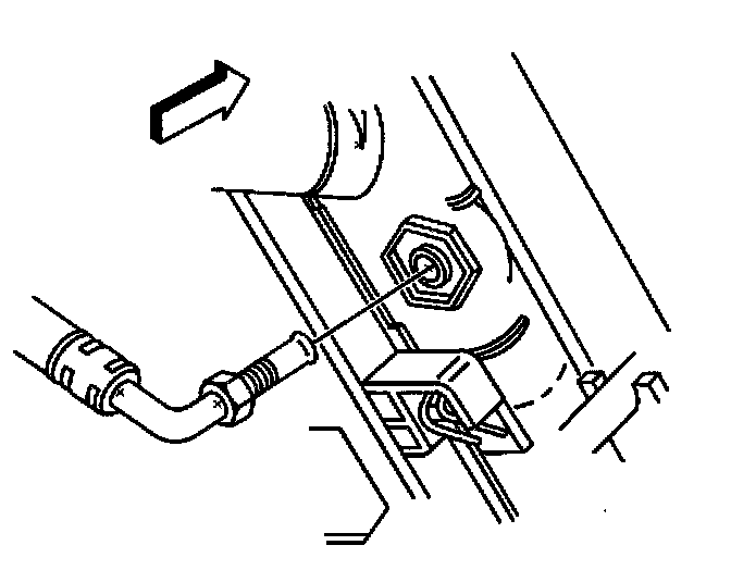
31. If equipped with the flared fitting design, remove the caps from the front of the TOO front upper and lower pipes and remove the plugs from the TOC.
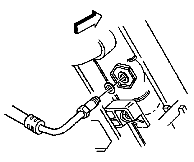
32. If equipped with the sealing washer design, remove the caps from the front of the TOC front upper and lower pipes, install new sealing washers, and remove the plugs from the TOC.
33. Flush the TOC and TOC pipes. Refer to AT Oil Cooler Flushing.
34. ALIGN and HAND-START, then tighten ONLY by hand to seat the TOC front lower pipe fitting to the radiator, if equipped with the flared fitting design.
^ Tighten the transmission oil cooler front lower pipe fitting to the radiator to 40 Nm (30 ft. lbs.).
35. ALIGN and HAND-START, then tighten ONLY by hand to seat the TOC front lower pipe fitting to the radiator, if equipped with the sealing washer design.
^ Tighten the transmission oil cooler front upper pipe fitting to the radiator to 16 Nm within 4 Nm (12 ft. lbs.. within 3 ft. lbs.).
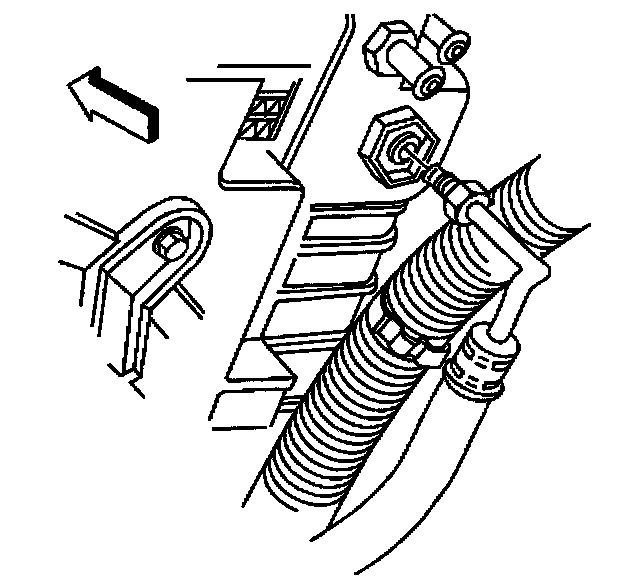
36. ALIGN and HAND-START, then tighten ONLY by hand to seat the TOC front upper pipe fitting to the radiator, if equipped with the flared fitting design.
^ Tighten the transmission oil cooler front upper pipe fitting to the radiator to 40 Nm (30 ft. lbs.).
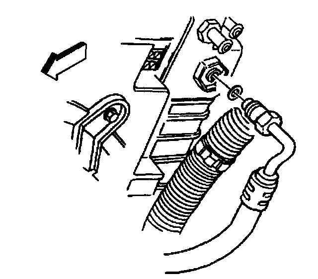
37. ALIGN and HAND-START, then tighten ONLY by hand to seat the TOC front upper pipe fitting to the radiator, if equipped with the sealing washer design.
^ Tighten the transmission oil cooler front upper pipe fitting to the radiator to 16 Nm within 4 Nm (12 ft. lbs.. within 3 ft. lbs.).
38. Lower the vehicle.
39. Connect the negative battery cable.
^ Tighten the negative battery cable bolt to 15 Nm (11 ft. lbs.).
40. Program the transmitters. Refer to Transmitter Programming/Synchronization in Accessories and Optional Equipment.
41. Refill the engine cooling system. Refer to Draining and filling Cooling System in Cooling System.
42. Evacuate and charge the A/C refrigerant system.
43. Check the transmission fluid level. Refer to Transmission Fluid Checking Procedure.