Front Camber Adjustment
The steps outlined in this procedure are general requirements for properly setting the front camber.The alignment equipment varies in design and capabilities, therefore, consult with the equipment manufacturer's guidelines prior to setting this angle.
1. Raise and support the front of the vehicle with a jack or with the alignment equipment.
2. Remove the front tire and wheel assembly from the vehicle. Refer to TIRE AND WHEEL REMOVAL AND INSTALLATION in TIRES AND WHEELS.
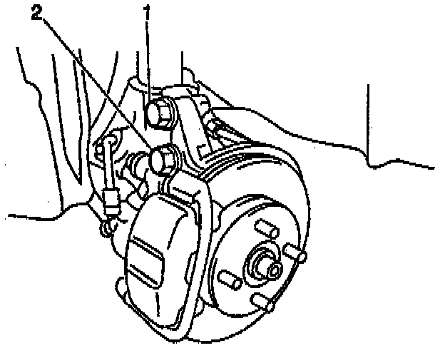
3. Remove the two nuts (1,2) on the lower side of the strut.
4. Coat the nut's threads with engine oil.
5. Temporarily install the two nuts.
NOTICE: Always use the correct fastener in the proper location. When you replace a fastener, use ONLY the exact part number for that application. The manufacturer will call out those fasteners that require a replacement after removal. The manufacturer will also call out the fasteners that require thread lockers or thread sealant. UNLESS OTHERWISE SPECIFIED, do not use supplemental coatings (paints, greases, or other corrosion inhibitors) on threaded fasteners or fastener joint interfaces. Generally, such coatings adversely affect the fastener torque and joint clamping force, and may damage the fastener. When you install fasteners, use the correct tightening sequence and specifications. Following these instructions can help you avoid damage to parts and systems.
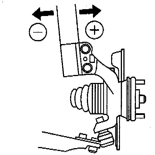
6. Adjust the camber by pushing or pulling the lower side of the strut in the direction in which the camber adjustment is required.
Tighten
Tighten 2 nuts to 274 Nm (203 ft. lbs.).
7. Install the tire and wheel assemblies. Refer to TIRE AND WHEEL REMOVAL AND INSTALLATION in TIRES AND WHEELS.
8. Inspect the alignment. Refer to WHEEL ALIGNMENT SPECIFICATIONS.
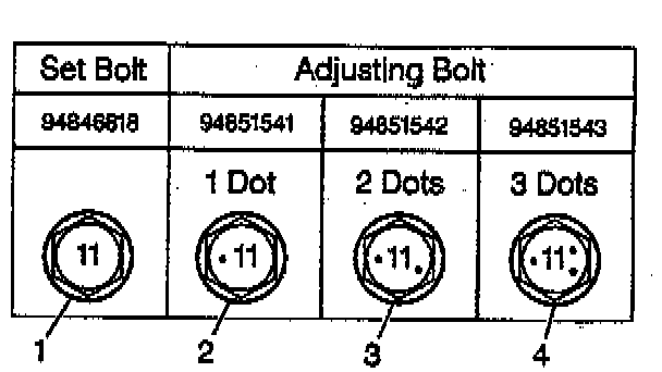
9. If the camber is not within the specified range estimate how much additional camber adjustment you require. Select the appropriate combination of bolts in order to obtain the following camber value:
^ In order to obtain 0.25° camber, use 94846618 (1) in the upper bolt position, and 94851541 (2) in the lower bolt position.
^ In order to obtain 0.50° camber, use 94846618 (1) in the upper bolt position, and 94851542 (3) in the lower bolt position.
^ In order to obtain 0.75° camber, use 94846618 (1) in the upper bolt position, and 94851543 (4) in the lower bolt position.
^ In order to obtain 1.00° camber, use 94851541 (2) in the upper bolt position, and 94851543 (4) in the lower bolt position.
^ In order to obtain 1.25° camber, use 94851542 (3) in the upper bolt position, and 94851543 (4) in the lower bolt position.
^ In order to obtain 1.50° camber, use 94851542 (4) in the upper bolt position, and 94851542 (4) in the lower bolt position.
10. Install the selected bolt for the upper bolt position.
11. Install the selected bolt for the lower bolt position.
12. Repeat steps 4-11 until the camber is within the specified range.