- Powertrain/On-Board Diagnostic System Check
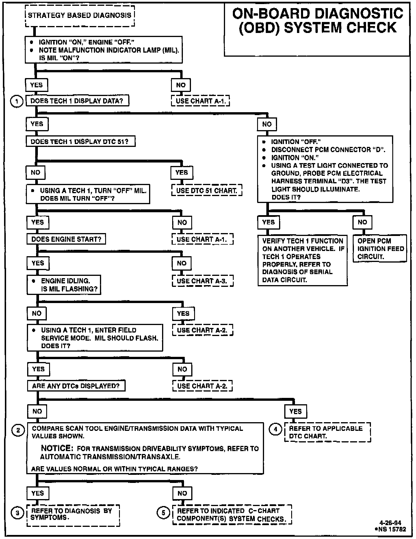
On-Board Diagnostic (OBD) System Check:
PCM Power Supply,MIL And DLC Circuits:
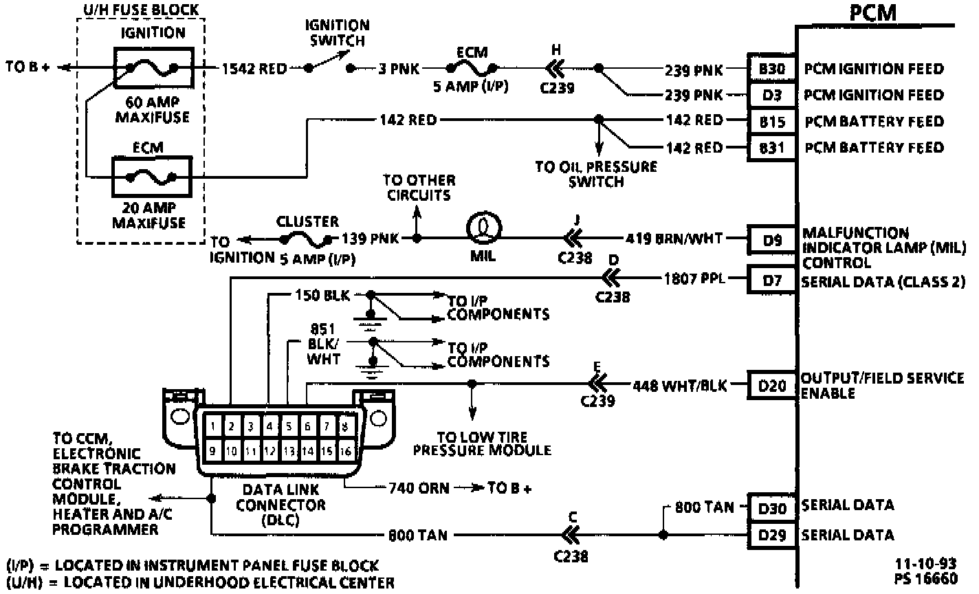
CIRCUIT DESCRIPTION
The On-Board Diagnostic (OBD) system check is an organized approach to identifying a problem created by an electronic engine control system malfunction. It must be the starting point for any driveability complaint diagnosis, because it directs the service technician to the next logical step in diagnosing the complaint. Understanding the chart and using it correctly will reduce diagnostic time and prevent the unnecessary replacement of good parts.
CHART TEST DESCRIPTION
Number(s) below refer to circled number(s) on the diagnostic chart.
1. This step is to determine if the Tech 1 can establish communication with the Powertrain Control Module (PCM). If there is no communication between the PCM and the Tech 1, no data will be displayed. Faulty connections or an open PCM ignition feed to "D3" can also cause this problem. If circuit and connections check OK, refer to Information Bus for serial data circuit diagnosis.
2. Comparison of actual control system data with the typical values is a quick check to determine if any parameter is not within limits. Keep in mind that a base engine problem (i.e. advanced cam timing) may substantially alter sensor values.
3. Installation of a scan tool will provide a ground path for the PCM and may hide a driveability complaint due to poor PCM grounds.
4. If multiple DTCs are stored, start with the lowest numbered DTC first, unless DTC chart indicates not to.
5. If the actual data is not within the typical values established, the C-Charts in System Diagnosis / Procedures will provide a functional check of the suspect component or system.
NOTE: This vehicle is equipped with a Powertrain Control Module (PCM) utilizing an Electrically Erasable Programmable Read Only Memory (EEPROM). When diagnostics call for replacement of the PCM, the new PCM must be programmed. Refer to Powertrain Control Module / Service and Repair. Service and Repair
DIAGNOSTIC AIDS
Inspect all related wiring and connections including the connections at the PCM. these may cause an intermittent malfunction. Check for damaged, corroded or pushed out terminals.