Diagnostic Notes
Ignition System:
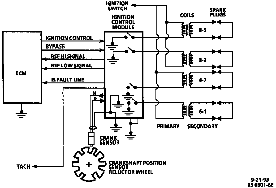
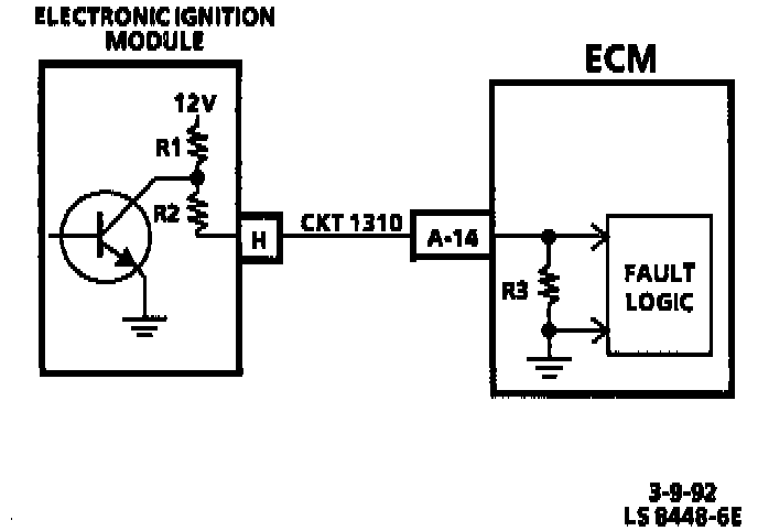
EI Fault Line Circuit:
For a electronic ignition system / misfire check, refer to Chart C-4 Ignition System Check. Chart C-4 Ignition System Check
RESULT OF INCORRECT OPERATION
An open or ground in the Electronic Ignition (EI) fault line will set DTC 16. An open or ground in the IC, or bypass circuit will set a DTC 36 or DTC 42 and cause the engine to run on the ignition control module timing. This will cause reduced performance and poor fuel economy.
The ECM uses information from the MAP and engine coolant temperature sensors in addition to RPM to calculate spark advance as follows:
Cold engine = More spark advance.
Engine under minimum load based on RPM and low amount of air flow = More spark advance.
Hot engine = Less spark advance.
Engine under heavy load based on RPM and high amount of air flow = Less spark advance.
DTC 12
DTC 12 is used during the On-Board Diagnostic System Check procedure to test the DTC display ability of the ECM. This DTC indicates that the ECM is not receiving the engine RPM "Reference" signal. This occurs with the ignition "ON" and the engine not running.
The "Reference" signal also triggers the fuel injection system. Without the "Reference" signal the engine cannot run. This signal can be checked by monitoring RPM using a scan tool. The "Reference" signal can help determine the cause of an engine that cranks but will not start.
HOW DTC 16 IS DETERMINED
The EI fault line (CKT 1310) output to the ECM will normally be in the high state (logic high), which is approximately 7.1 volts. If the EI fault line remains grounded or open for 4.5 seconds or longer, the ECM will store a DTC 16 in memory, and turn "ON" the Malfunction Indicator Lamp (Service Engine Soon) as long as the fault occurs. The ECM will remove the 5 volt bypass line anytime the EI fault line goes low. If the EI fault line goes back to normal after a DTC 16 has been set, the Malfunction Indicator Lamp (Service Engine Soon) will go out, the ECM will apply the 5 volt bypass to the ignition control module and Ignition Control (IC) mode will be resumed. The EI fault line will be in the low state anytime that the ignition control module detects a fault that forces the ignition control module to go back to bypass mode.
HOW DTC 36 IS DETERMINED
DTC 36 can be set when more IC pulses from the ECM are sensed by the ignition control module than the number of pulses being sent out on the reference high signal (CKT 430). When this happens the ignition control module will return to bypass mode, even though the ECM is still applying 3 volts to the bypass (CKT 424) line, and output a low state on the EI fault line. If the IC input returns to normal, the ignition control module will return to the IC mode and Output a high state on the EI fault line.
DTC 36 can also be set if the engine is running in the IC mode (greater than 400 RPM) and the IC signal is missing (no high to low transitions) for two crankshaft revolutions:
- The ignition control module switches itself back to bypass mode with retarded ignition timing.
- The EI fault line will go low to signal the ECM a problem exists.
- The ECM will respond by taking the 5 volts bypass line low (turned "0FF").
- The module will respond by bringing the EI fault line back to a high state.
- The ECM will retest the IC circuit by turning back "ON" the 5 volts bypass line.
- If the ignition control module still detects a fault in the IC line, it will remain in bypass mode and it will pull the EI fault line low.
- The ECM will turn "OFF" and turn "ON" the bypass line as many as 10 times before setting DTC 36 during one ignition cycle.
If a DTC 16 and DTC 36 is found stored in memory, the DTC 16 chart should be used first.
HOW DTC 4215 DETERMINED
The Ignition Control (IC) signal (CKT 423) is monitored during cranking by the ECM. The voltage level if measured on a scope should be less than 1.3 volts at a high state and near 0 volt at a low state during cranking (engine RPM less than 400). If the ECM detects the high to low signal to be different than 0-to-1.3 volts transitions, a DTC 42 is set.
When the electronic ignition system is running on ignition control module timing, less than 400 RPM, the ECM does not apply 5 volt to the ignition control module on the bypass line. The ECM applies an IC signal to the ignition control module, but because the bypass input is low, the module will pull the IC signal low, and ignore the IC signal. There is an IC monitor, internal to the ECM, that measures the IC amplitude. Below 400 RPM the ECM should monitor the IC signal as being pulled low.
When the reference signal to the ECM indicates the engine is rotating faster than 400 RPM, the ECM will apply 5 volts on the bypass line. When the ignition control module senses the 5 volts on the bypass line, it will unground the IC signal and use the IC signal for determining spark timing. The ECM will set DTC 42 if the reference signal indicates the engine RPM is above 450, it has sent 5 volts to the module but the IC monitor in the ECM has no~ seen the IC signal in a high state, ungrounded. This may be caused by a fault in the bypass line (CKT 424), or possibly a module that does not unground the IC signal, or a fault in the IC circuit. Ignition timing will not be interrupted during this fault transition. DTC 42 will usually be set when there is a fault present when the engine is cranking.
A sluggish driveability condition will result at initial launches and low RPM operations when DTC 42 is set.