Intake Manifold Assembly (On Vehicle)
Remove or Disconnect
Fuel Rail and Throttle Body Assemblies:
Intake Manifold Assembly:
Intake Manifold Tightening Sequence:
1. Battery negative cable.
2. Drain coolant.
3. Throttle body air duct.
4. Fuel rail covers.
5. Wiring harness connectors from fuel injectors.
6. Relieve fuel system pressure..
7. Left and right wiring harnesses and lay aside.
8. Accelerator cable bracket bolts/screws, bracket and cables from throttle body assembly.
9. Secondary air injection diverter valve hoses.
10. Electrical ground strap from intake manifold assembly.
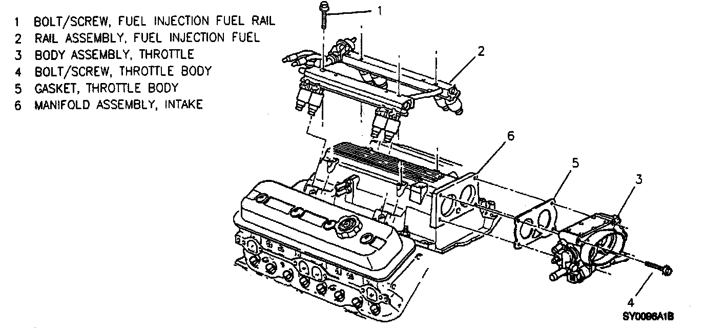
11. Fuel rail bolts/screws (1).
12. Fuel pressure regulator vacuum tube assembly.
13. Fuel rail assembly (2) from intake manifold assembly (6) and lay aside.
14. Vacuum and crankcase vent hoses.
15. Exhaust gas recirculation (EGR) control valve nut and control valve assembly.
16. Emission canister purge control valve bracket nut and control valve.
17. EGR valve bolts/screws and EGR valve assembly.
18. Secondary air injection pipe assembly from intake and right exhaust manifold assemblies.
19. Generator brace.
20. Coolant hoses from throttle body assembly.
21. Throttle body bolts/screws (4), throttle body assembly (3) and gasket (5).
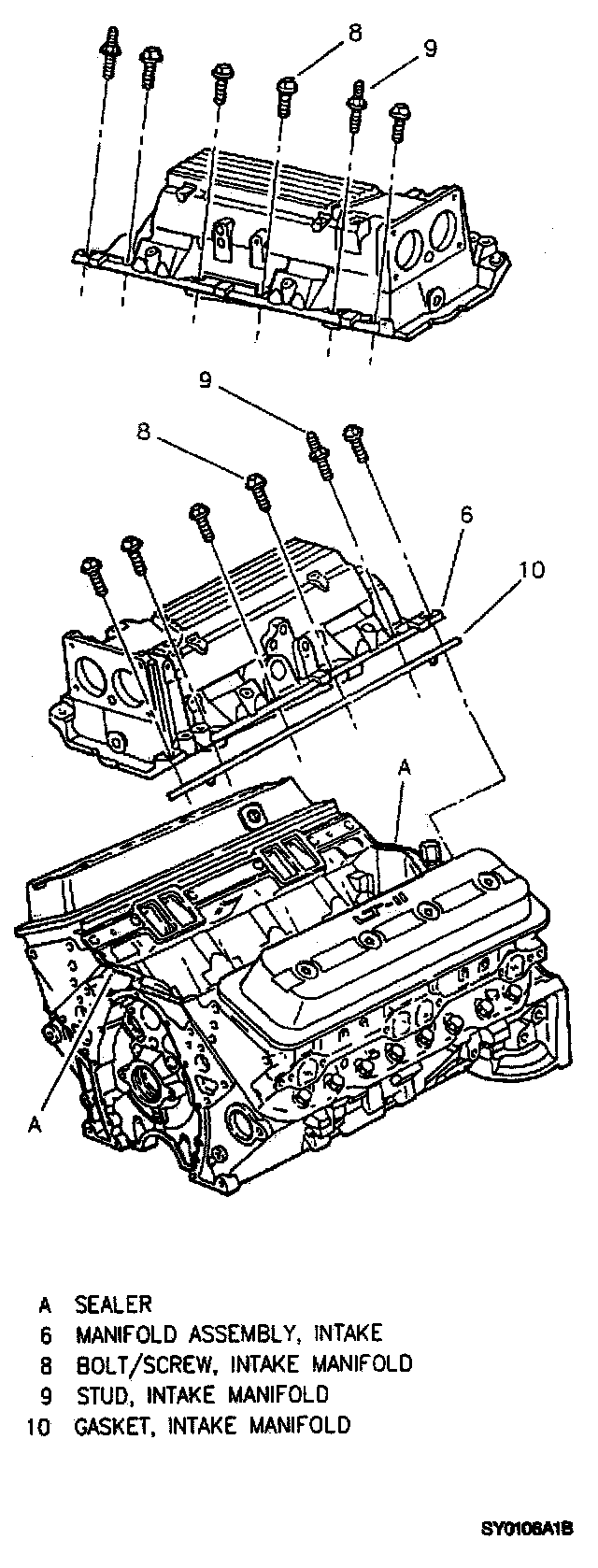
22. Intake manifold bolts/screws (8) and studs (9).
23. Intake manifold assembly (6) and gaskets (10).
^ Discard gaskets (10).
Clean
^ Intake manifold bolts/screws (8) and studs (9).
^ Cylinder head, engine block and intake manifold sealing surfaces.
Install or Connect
Fuel Rail and Throttle Body Assemblies:
Intake Manifold Assembly:
Intake Manifold Tightening Sequence:
1. Apply a 5 mm (3/16 inch) bead of RTV sealer, GM P/N 12346141 or equivalent, to the front and rear of the engine block. Extend the bead 13 mm (1/2 inch) up each cylinder head assembly to seal and retain the gaskets.
2. Intake manifold assembly (6) with new gaskets (10).
3. Intake manifold bolts/screws (8) and studs (9).
Tighten
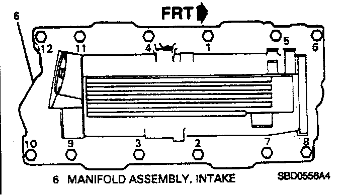
^ Intake manifold bolts/screws (8) and studs (9) in first pass to 8 Nm (71 lb in) in sequence as illustrated.
^ Tighten in sequence in a second pass to final specification of 48 Nm (35 ft lb).
4. Throttle body assembly (3), gasket (5) and bolts/screws (4).
Tighten
^ Throttle body bolts/screws (4) to 25 Nm (18 ft lb).
5. Coolant hoses to throttle body assembly.
6. Generator brace.
7. Accelerator cable bracket and cables.
Tighten
^ Accelerator cable bracket bolts/screws to 10 Nm (89 lb in).
8. Secondary air injection pipe assembly.
Tighten
^ Secondary air injection pipe exhaust manifold fitting to 55 Nm (41 ft lb).
^ Secondary air injection pipe flange bolts/screws to intake manifold assembly to 26 Nm (19 ft lb).
^ Secondary air injection pipe bracket bolt/screw to cylinder head assembly to 34 Nm (25 ft lb).
9. EGR valve assembly and bolts/screws.
10. EGR control valve assembly and nut.
Tighten
^ ECIR valve bolts/screws to 25 Nm (18 ft lb).
^ ECIR control valve nut to 25 Nm (18 ft lb).
11. Emission canister purge control valve and bracket nut.
Tighten
^ Emission canister purge control valve bracket nut to 20 Nm (15 ft lb).
12. Vacuum and crankcase vent hoses.
13. Fuel rail assembly (2) to intake manifold assembly (6).
14. Fuel pressure regulator vacuum tube assembly.
15. Fuel rail bolts/screws (1).
Tighten
^ Fuel rail bolts/screws (1) to 10 Nm (89 ft lb).
16. Electrical ground strap to intake manifold assembly.
17. Secondary air injection diverter valve hoses.
18. Left and right wiring harnesses.
19. Wiring harness connectors to fuel injectors.
^ Match proper electrical connector with fuel injector according to cylinder number marked on electrical connector.
20. Throttle body air duct.
21. Fuel rail covers.
22. Refill with coolant.
23. Battery negative cable.
Adjust
^ ASR control cables.