Intake Manifold: Service and Repair
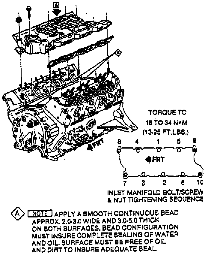
REMOVE OR DISCONNECT
1. Battery ground cable
2. Accelerator and T.V. cable bracket at the plenum
3. Throttle body at the plenum
4. EGR pipe at the EGR valve
5. Plenum
6. Fuel inlet and return pipes at the fuel rail
7. Serpentine belt
8. Power steering pump mounting bracket
9. Heater coolant pipe at the power steering pump bracket
10. Wires at the generator
11. Generator
12. Wires at the cold start injector
13. Cold start injector at the intake manifold
14. Idle air vacuum hose at the throttle body
15. Wires at the injectors
16. Fuel rail
17. Breather tube
18. Runners
19. Coil wires at the bracket
20. Both rocker arm covers
21. Drain the c9oling system.
22. Radiator hose at the thermostat outlet
23. Heater coolant pipe at the thermostat housing
24. Wires at the thermostat housing
25. Ignition distributor
26. Thermostat housing
27. Intake manifold bolts
28. Intake manifold
CLEAN
^ Gasket material
^ Loose RTV from front and rear ridges of cylinder block
^ Sealing surfaces with degreaser
INSTALL OR CONNECT
1. Place a 3mm diameter (3/16") bead of GM 1052917. RTV sealer or equivalent on each ridge.
2. Intake gaskets
3. Cut the new gaskets where indicated to clear push rods
^ Make sure areas between case ridges and intake are completely sealed
4. Intake manifold on engine
5. Manifold bolts and nuts
Tighten
^ In the sequence shown 31 Nm (23 lbs. ft.)
7. Thermostat housing
8. Distributor
9. Wires at thermostat housing
10. Heater pipe at the thermostat housing
11. Radiator hose at the thermostat outlet
12. Fill cooling system.
13. Rocker arm cover as previously outlined
14. Coil wires at the bracket
15. Runner
16. Breather tube
17. Fuel rail
18. Wires at the injectors
19. Idle air vacuum hose at the throttle body
20. Cold start injector
21. Generator
22. Wires at the generator
23. Heater coolant pipe at the P/S pump bracket
24. P/S pump mounting bracket
25. Serpentine belt
26. Fuel inlet and return pipes at the fuel rail
27. Plenum
28. EGR valve pipe
29. Throttle body at the plenum
30. Accelerator and T.V. cable bracket at the plenum
31. Start engine, set initial timing.
Tighten Distributor clamp bolt 34 Nm (25 lbs. ft.)
32. Let engine run until radiator upper hose becomes hot (thermostat open).
33. With engine idling add coolant to cooling system, if necessary, until level reaches bottom of filler pipe.
34. Cooling system pressure cap, making sure arrows on cap line up with overflow tube
INSPECT
^ For proper timing adjustment
^ Coolant level
^ For fluid leaks