Rear Axle - Assemble
Rear Axle - Assemble^ Tool Required
- J 8001 Dial Indicator Set
- J 42155 Differential Lifting Tool
- J 42157 Left Output Shaft Bearing Installer
- J 42164 Pinion Gear Holder
- J 42170 Bearing and Race Installer
- J 42173 Differential Holding Fixture
- J 46405 Output Shaft Seal Installer
Important: If the pinion assembly components have not been replaced, reuse the original pinion housing shims. If the pinion assembly components have been replaced, refer to Drive Pinion Shim Selection for selection of the proper size shims.
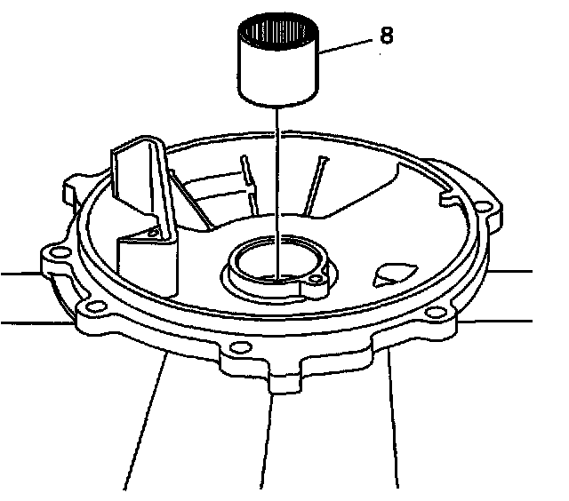
1. Assemble the drive pinion prior to rear axle assembly.
2. Install the bearing (8) to the cover - left.
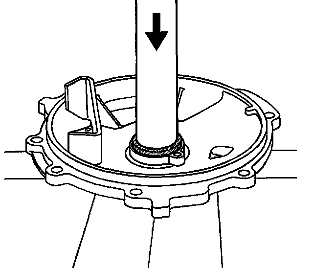
3. Install the bearing into the cover - left using the J42157 and a hydraulic press.
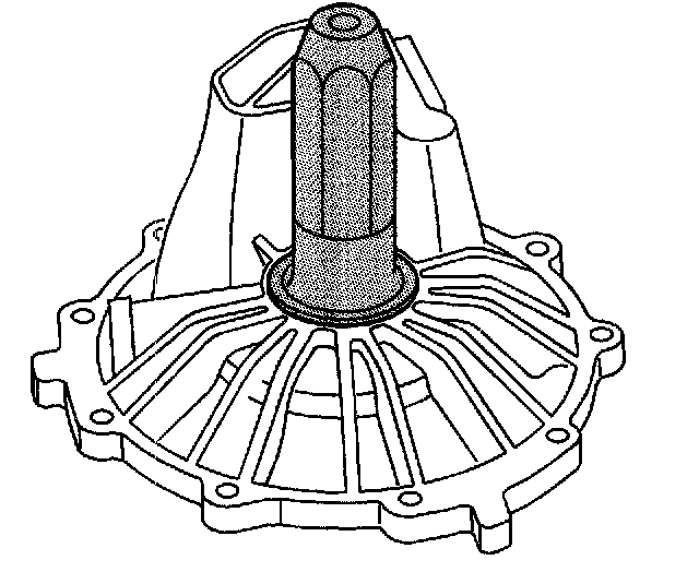
4. Install the oil seal into the cover - left using the J 46405.
5. Install the oil seal into the cover - right using the J 46405.
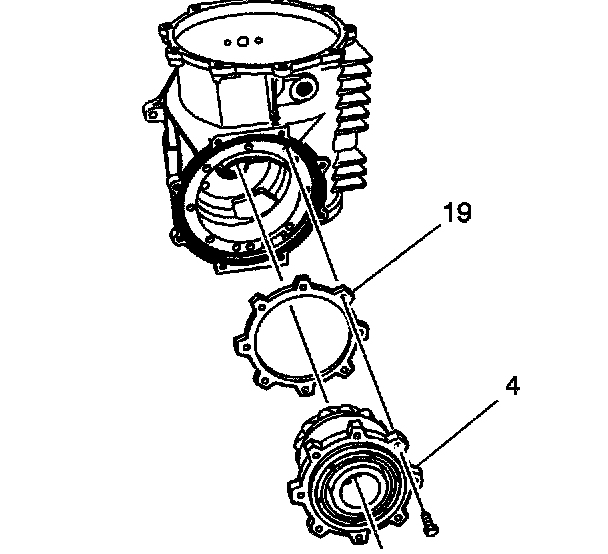
6. Install the pinion housing assembly (4) and the selected shim or shims (19) to the differential housing. Refer to Drive Pinion Shim Selection for shim selection.
The use of M8 x 1.25 dowels or long bolts will ease in pinion housing/cage and shim installation and alignment.
Notice: Refer to Fastener Notice in Service Precautions.
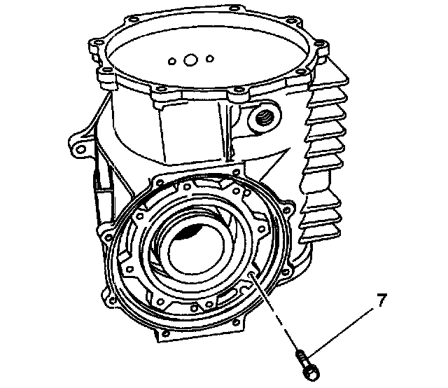
7. Install the pinion housing/cage bolts (7).
^ Tighten the bolts to 28 Nm (20 ft. lbs.).
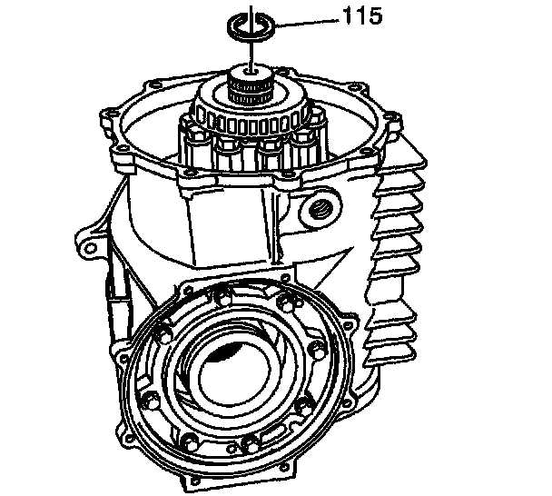
8. Install the C-clip (1115) into the groove of the output shaft.
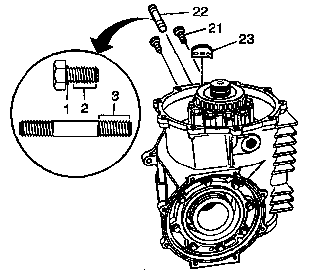
9. Apply threadlocker GM P/N 12345382 (Canadian P/N 10953489) or equivalent to the threads (2) of the bolts (21).
10. Apply sealant GM P/N 1052942 (Canadian P/N 10953466) or equivalent to the head (1) of the bolts (21), only to seal them. Also apply to the threads (3) of the stud (22) that goes into the carrier.
11. Install the adapter (23) and bolts (21).
^ Tighten the bolts to 10 Nm (89 inch lbs.).
12. Install 2 M10 x 1.5 nuts onto the transmission stud (22). Install the stud into the adapter.
^ Tighten the stud to 42 Nm (31 ft. lbs.).
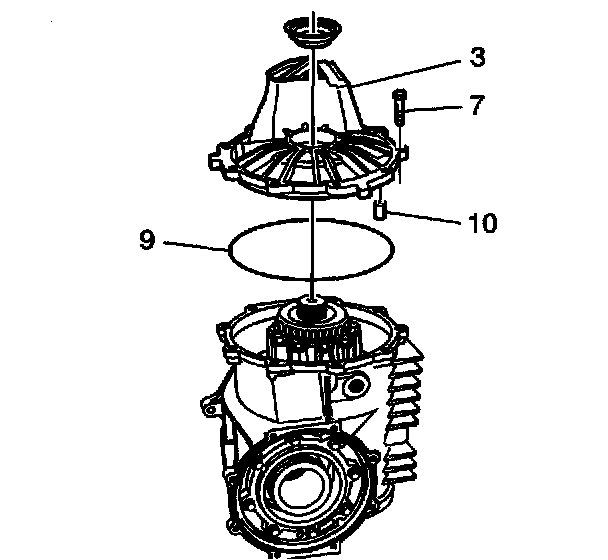
13. Install the O-ring (9) to the groove of the cover - right (3) and the dowel (10) into the carrier.
14. Install the cover - right and bolts (7).
^ Tighten the bolts to 25 Nm (18 ft. lbs.).
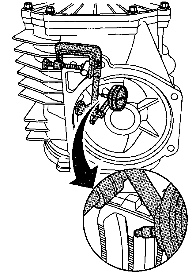
15. Install the J 8001 onto the transmission stud. Position the tip of the dial indicator against the center of the ring gear tooth surface.
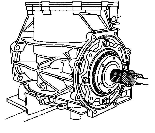
16. Install the J 42164 into the splines of the pinion. You must hold J 42164 to retain the pinion in order to properly measure backlash.
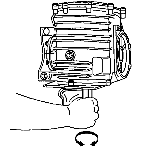
17. Move the output shaft - right in both directions in order to measure the gear backlash. Measure the backlash in two to three locations.
Important: Note the location of the cover - rear bolt for assembly.
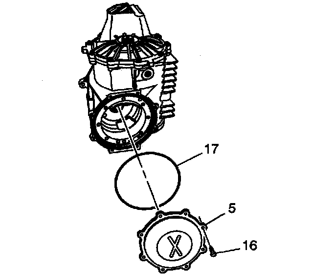
18. Install the cover - rear (5), bolt (16), and O-ring (17).
^ Tighten the bolt to 10 Nm (89 inch lbs.).
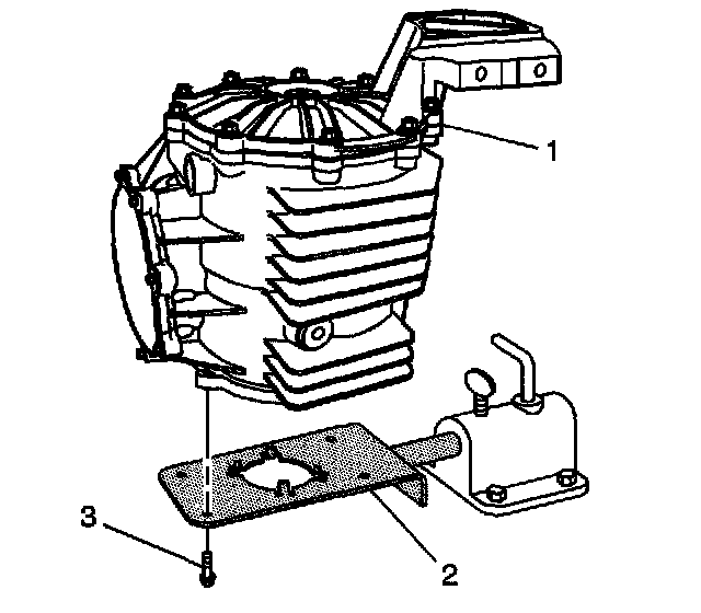
19. Remove the bolts (3) and the differential assembly (1) from the J 42173 (2).
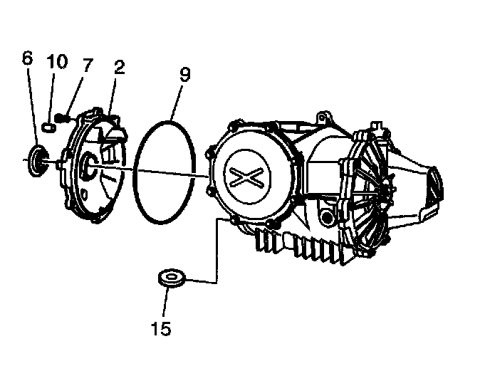
20. Install the O-ring (9) into the groove of the cover - left (2).
21. Install the magnet (15) and dowel (10) to the carrier.
22. Apply a continuous 3 mm (0.125 inch) bead of sealant GM P/N 1052942
(Canadian P/N 10953466) or equivalent to the left cover flange (2).
23. Apply sealant around the bolt holes. Keep sealant away from the O-ring.
24. Install the cover - left (2) and bolts (7).
^ Tighten the bolts to 28 Nm (20 ft. lbs.).
25. Clean the excess sealant from the left cover/housing split line.
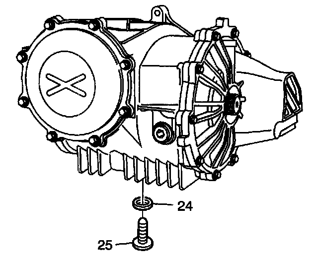
26. Install the drain plug (25) and washer (24).
^ Tighten the drain plug to 35 Nm (26 ft. lbs.).
27. Refer to Lubricant Replacement - Rear Drive Axle.