Brake Caliper Replacement - Front
Brake Caliper Replacement- FrontRemoval Procedure
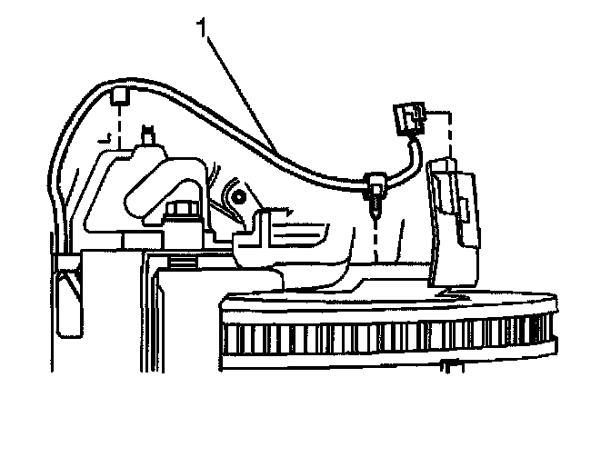
1. Inspect the fluid level in the brake master cylinder reservoir.
2. If the brake fluid level is midway between the maximum-full point and the minimum allowable level, no brake fluid needs to be removed from the reservoir before proceeding.
3. If the brake fluid level is higher than midway between the maximum-full point and the minimum allowable level, remove brake fluid to the midway point before proceeding.
4. Raise and support the vehicle. Refer to Vehicle Lifting.
5. Mark the relationship of wheel to the axle flange.
6. Remove the tire and wheel assembly.
7. Install and hand tighten 2 wheel lug nuts to retain the rotor to the hub.
8. Lift the electronic brake wear sensor retainer clip.
9. Remove the electronic brake wear sensor wire (1) from under the retainer clip.
10. Carefully pulling up on the electronic brake wear sensor wire and with a small screw driver push the retaining clip inward and remove the electronic brake wear sensor from the inner brake pad.
11. Disconnect the electronic brake wear sensor connector.
12. Remove the electronic brake wear sensor form the caliper.
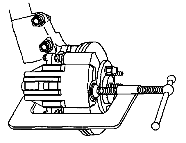
13. Install a large C-clamp over the body of the brake caliper with the C-clamp ends against the rear of the caliper body and against the outer brake pad.
14. Tighten the C-clamp until the caliper piston is compressed into the caliper bore enough to allow the caliper to slide past the brake rotor.
15. Remove the C-clamp from the caliper.
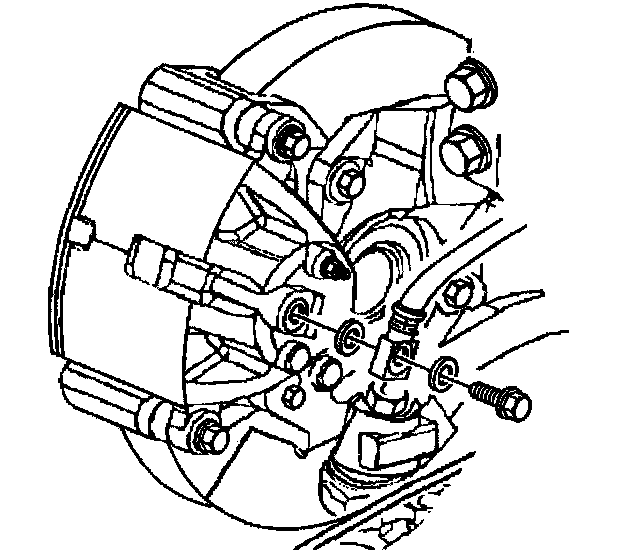
16. Remove the brake hose to caliper bolt from the brake caliper.
17. Remove and discard the two copper brake hose gaskets. These gaskets may be stuck to the brake caliper and/or the brake hose end.
18. Plug the opening in the brake caliper and hose to prevent fluid loss and contamination.
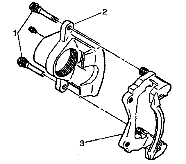
Important: The upper caliper pin bolt, has a bushing as part of the bolt. The lower caliper pin bolt, is o a solid design.
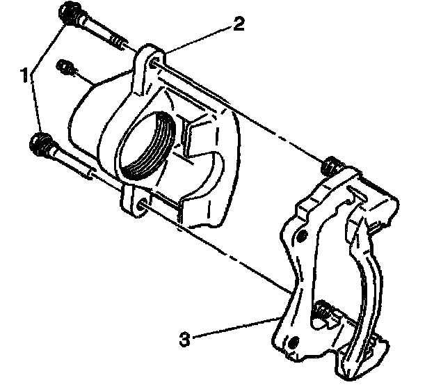
19. Remove the caliper pin bolts (1). Note the location of the caliper pin bolts.
20. Remove the caliper (2) from the caliper bracket (3).
21. Inspect the caliper pin bolt boots in the caliper bracket for the following conditions:
^ Cuts
^ Tears
^ Deterioration
Replace any damaged caliper pin bolt bolts.
Installation Procedure
1. If reusing the brake caliper pin bolts, wipe the old grease from the brake caliper pin bolts with a clean shop towel.
Important: DO NOT apply lubricant to the brake cad hardware.
2. Apply NIGLUBE grease to the brake caliper pin bolts. It is not necessary to apply lubricant to the brake pad hardware or the threads of the caliper pin bolts.
3. Install the brake caliper (2) over the brake pads into the brake caliper bracket (3).
Notice: Refer to Fastener Notice in Service Precautions.
Important: The upper caliper pin bolt, has a bushing as part of the bolt. The lower caliper pin bolt, is of a solid design.
4. Install the caliper pin bolts (1).
^ Tighten the brake caliper pin bolts to 85 Nm (63 lb ft).
Important: Install NEW copper brake hose gaskets.
5. Assemble the brake hose bolt and the NEW copper brake hose gaskets to the brake hose.
6. Install the brake hose to caliper bolt to the brake caliper.
^ Tighten the brake hose to caliper bolt to 45 Nm (33 lb ft).
7. Install the electronic brake wear sensor wiring (1) to the caliper.
8. Install the electronic brake wear sensor to the caliper.
9. Connect the electronic brake wear sensor connector.
10. Insert the electronic brake wear sensor into the inn brake pad.
11. Lift the electronic brake wear sensor retainer clip and install the wire under the clip.
12. Bleed the brake system.
13. With the engine OFF, gradually apply the brake pedal to approximately 2/3 of its travel distance.
14. Slowly release the brake pedal.
15. Wait 15 seconds, then repeat steps 13-14 until a firm brake pedal is obtained. This will properly seat the brake caliper pistons and brake pads.
16. Remove the two wheel lug nuts retaining the brake rotor to the hub.
17. Install the tire and wheel assembly.
18. Lower the vehicle.