Upper Intake Manifold Replacement
Upper Intake Manifold Replacement
Removal Procedure
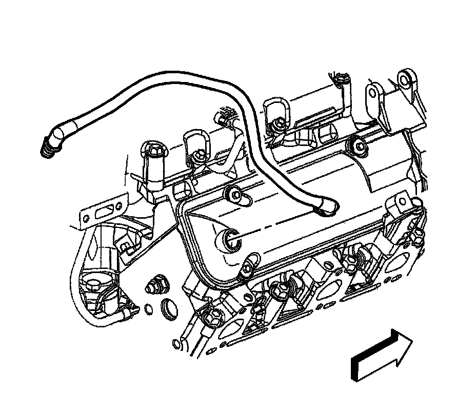
1. Drain the cooling system.
2. Remove the intake manifold cover.
3. Remove the air cleaner outlet duct.
4. Disconnect the evaporative emission (EVAP) canister purge solenoid valve quick connect fitting.
5. Remove the positive crankcase ventilation (PCV) fresh air tube from the rocker cover.
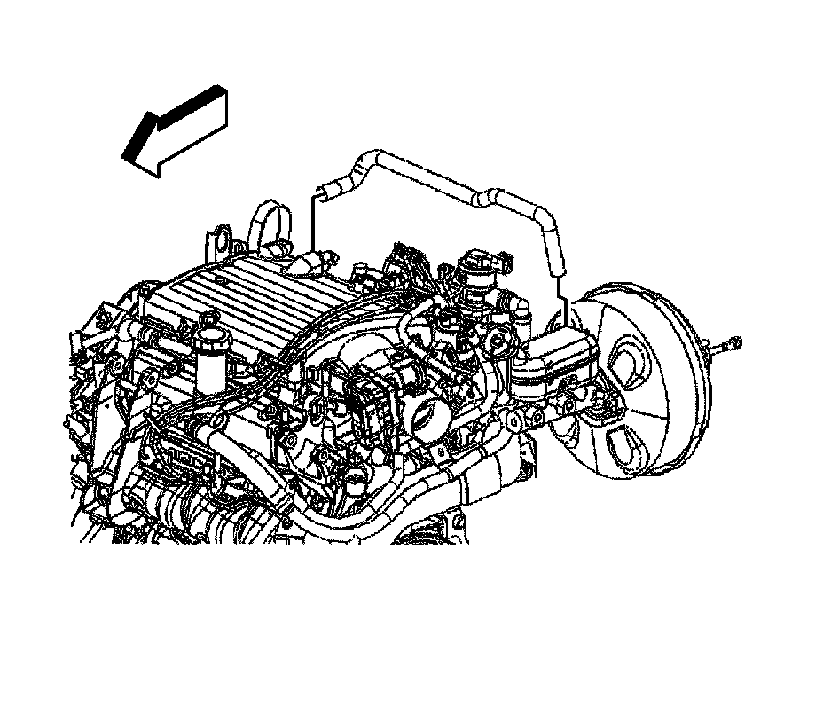
6. Reposition the brake booster vacuum hose clamp at the intake manifold.
7. Remove the brake booster vacuum hose from the intake manifold.
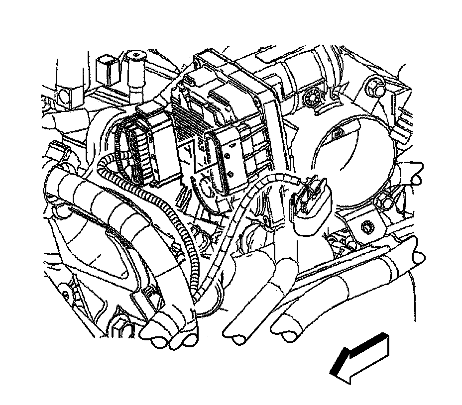
8. Disconnect the electronic control module electrical connector.
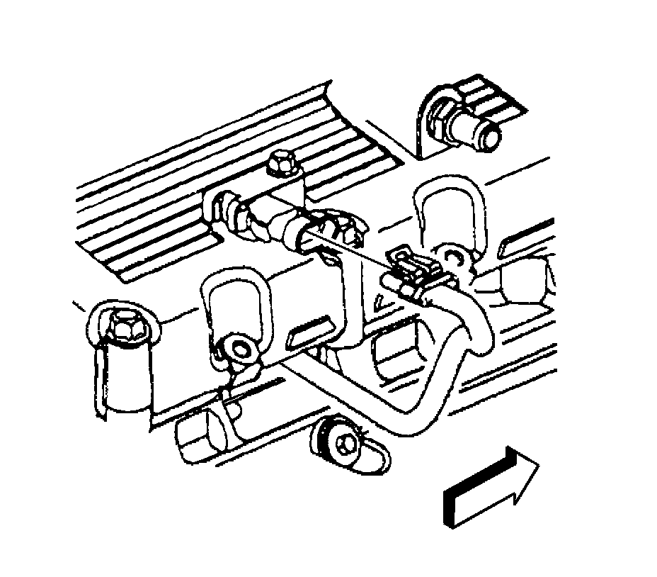
9. Disconnect the manifold absolute pressure (MAP) sensor electrical connector.
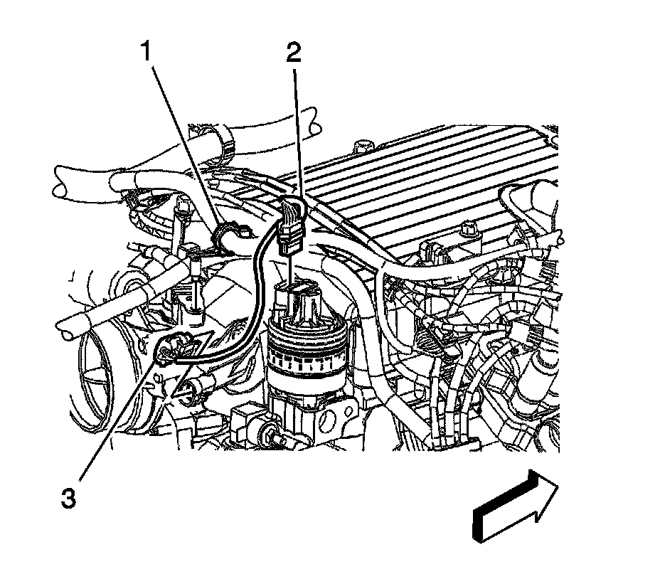
10. Remove the engine harness clip (1) from PCV foul air clip.
11. Disconnect the exhaust gas recirculation (EGR) valve electrical connector (2).
12. Disconnect the EVAP canister purge solenoid valve electrical connector (3).
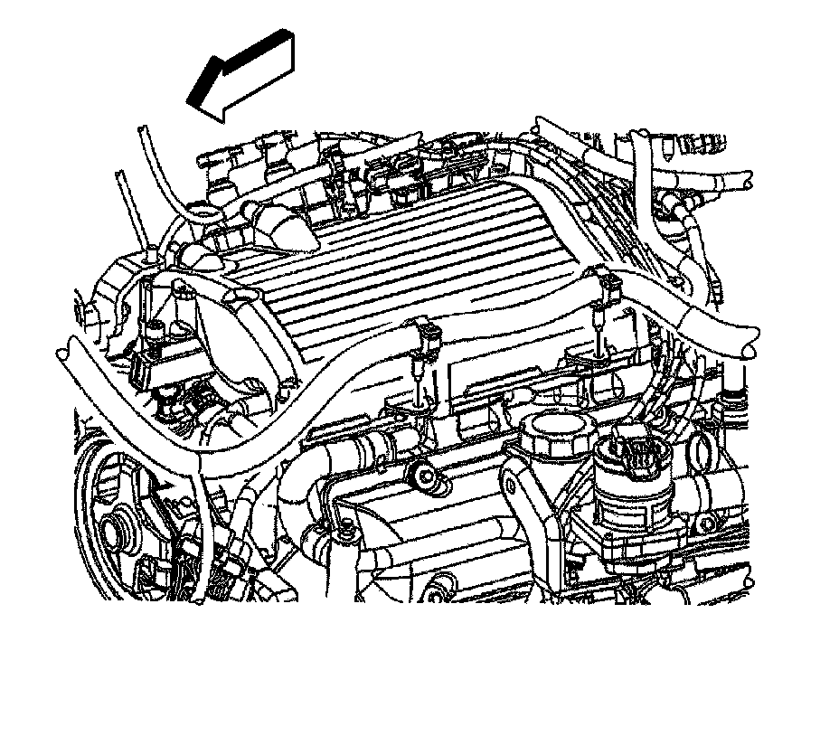
13. Remove the engine harness clips from the intake manifold.
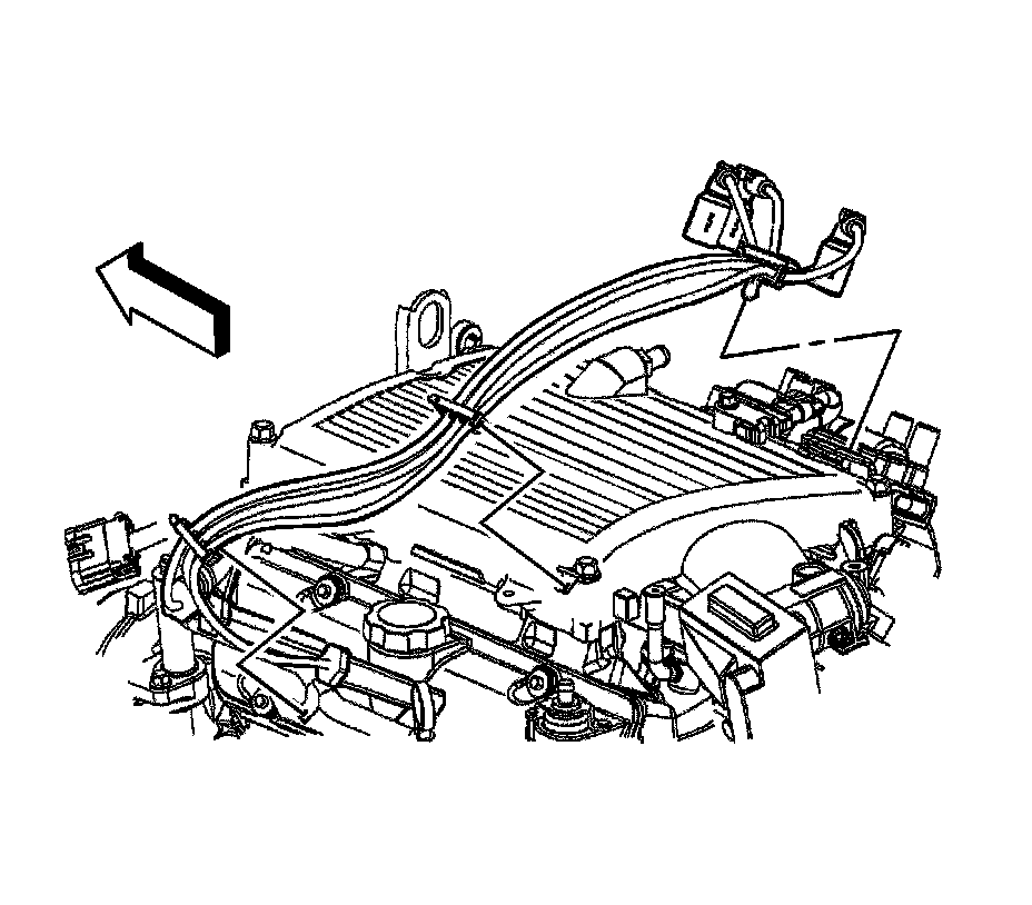
14. Disconnect the spark plug wires from the ignition coil.
15. Remove spark plug wire harness clips from the following:
* Ignition coil bracket
* Spark plug wire support
* Coolant bypass pipe
16. Disconnect the spark plug wires from the spark plugs.
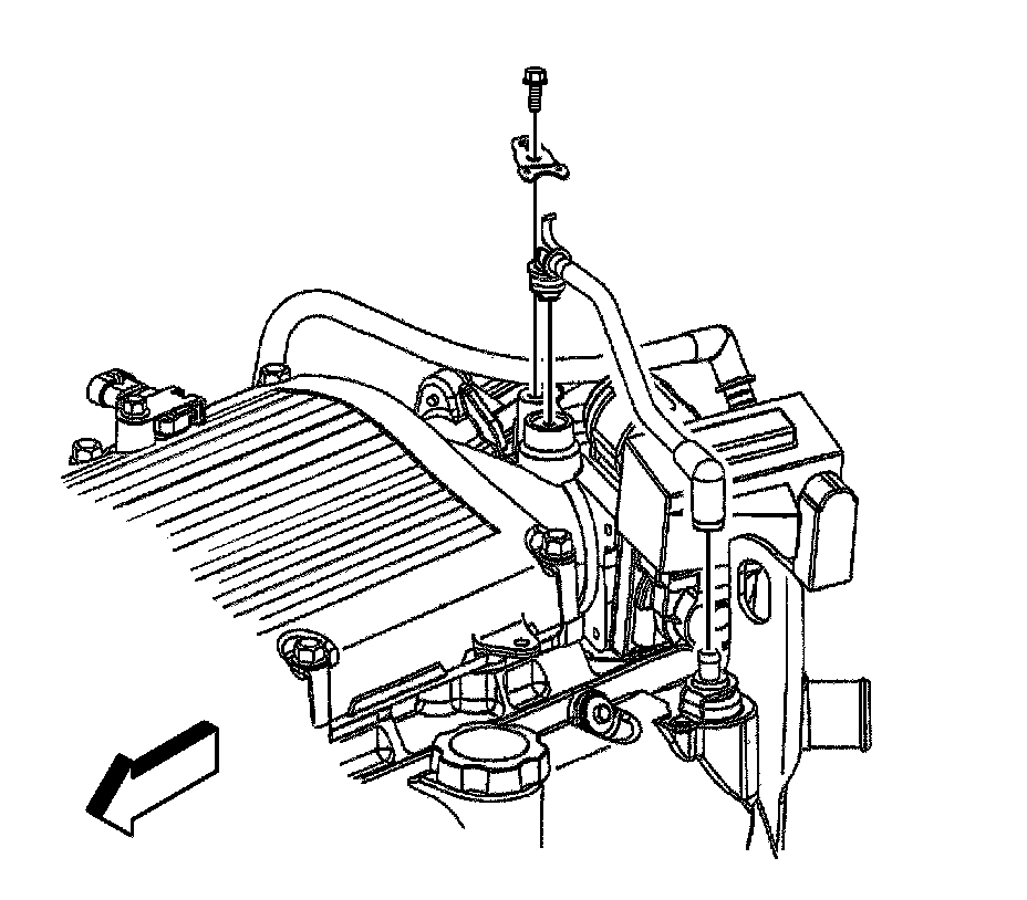
17. Remove the PCV foul air tube bolt.
18. Remove the PCV foul air tube clip.
19. Remove the PCV foul air tube.
20. Remove the thermostat bypass pipe.
21. Remove the ignition coil.
22. Remove the EGR valve.
23. Remove the generator bracket.
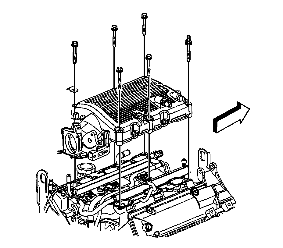
24. Remove the upper intake manifold bolts and stud.
25. Remove the spark plug support bracket.
26. Remove the upper intake manifold.
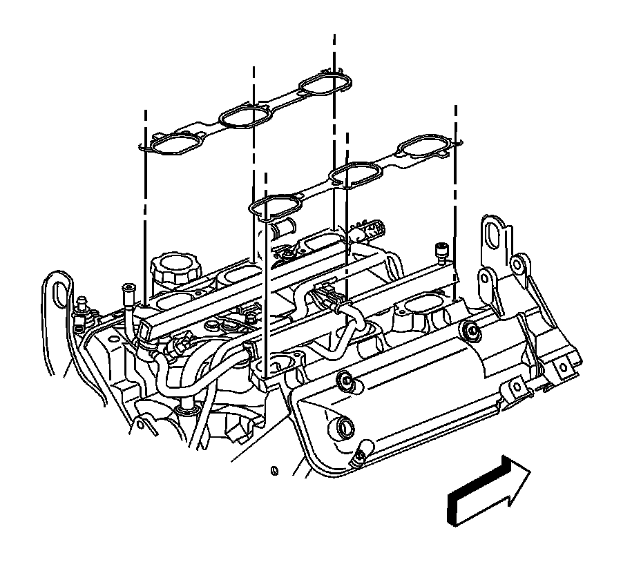
27. Remove the upper intake manifold to lower intake manifold gaskets.
28. Clean the upper and lower intake gasket mating surfaces.
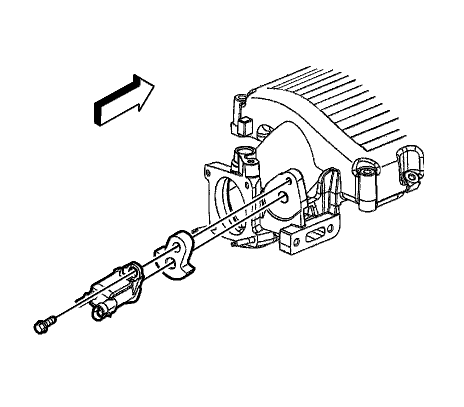
29. If replacing the upper intake manifold, perform the following steps, remove the EVAP canister purge solenoid valve bolt.
30. Remove the EVAP canister purge solenoid valve and insulator.
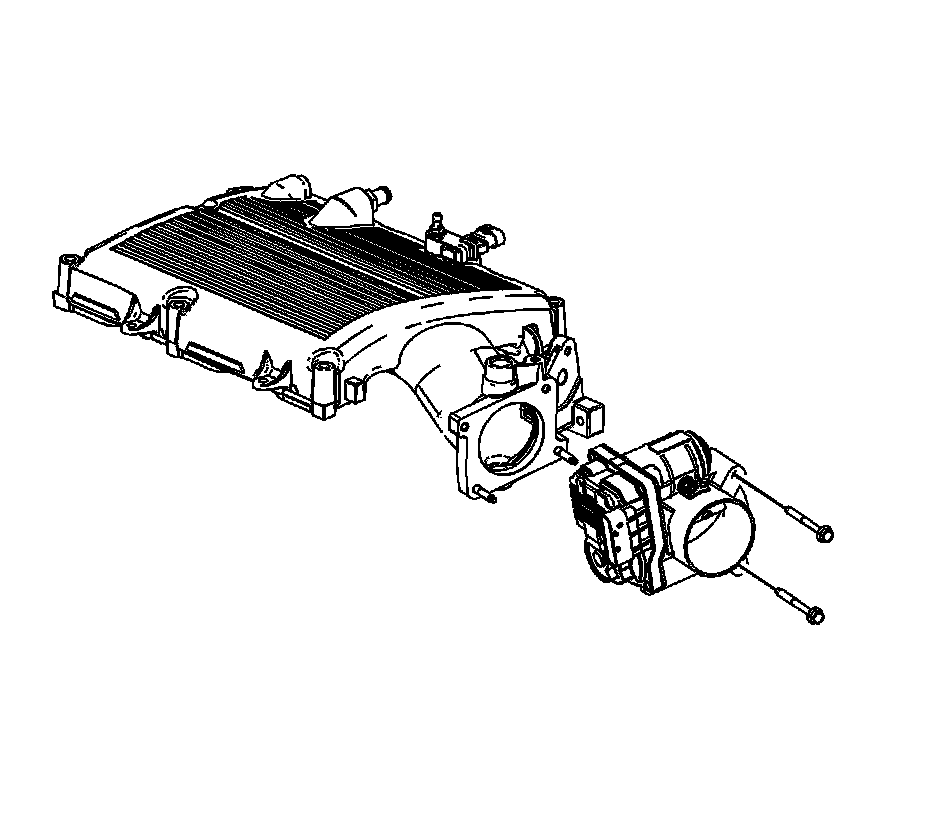
31. Remove the throttle body bolts.
32. Remove the throttle body.
33. Remove and inspect the throttle body seal, replace as necessary.
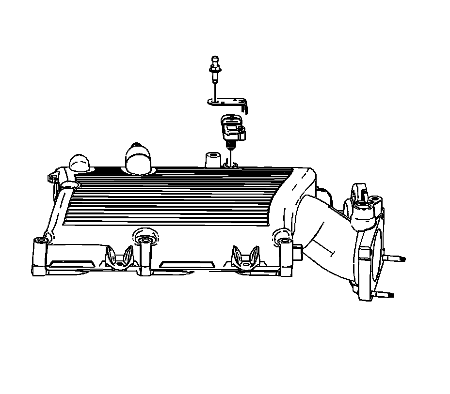
34. Remove the MAP sensor bolt.
35. Remove the MAP sensor bracket and sensor.
36. Remove and inspect the throttle body seal, replace as necessary.
Installation Procedure
1. If the intake manifold was replaced perform the following steps, if not proceed to step 10.
2. Install the MAP sensor seal.
3. Install the MAP sensor bracket and sensor.
Notice: Refer to Fastener Notice.
4. Install the MAP sensor bolt.
Tighten the bolt to 10 N.m (89 lb in).
5. Install the throttle body seal.
6. Install the throttle body.
7. Install the throttle body bolts.
Tighten the bolts to 10 N.m (89 lb in).
8. Position the EVAP canister purge solenoid valve insulator and valve to the intake.
9. Install the EVAP canister purge solenoid valve bolt.
Tighten the bolt to 12 N.m (106 lb in).
10. Install NEW upper intake manifold to lower intake manifold gaskets.
11. Install the upper intake manifold.
12. Apply threadlock to the upper intake manifold bolt threads. Refer to Sealers, Adhesives, and Lubricants for the correct part number.
13. Install the spark plug support bracket onto one bolt, install the bolt.
14. Install the other upper intake manifold bolts and stud.
Tighten the bolts/stud to 25 N.m (18 lb ft).
15. Install the generator bracket.
16. Install the EGR valve.
17. Install the ignition coil.
18. Install the thermostat bypass pipe.
19. Install the PCV foul air tube.
20. Position the PCV foul air tube clip.
21. Install the PCV foul air tube bolt.
Tighten the bolt to 10 N.m (89 lb in).
22. Connect the spark plug wires to the ignition coil.
23. Install spark plug wire harness clips to the following:
* Ignition coil bracket
* Spark plug wire support
* Coolant bypass pipe
24. connect the spark plug wires to the spark plugs.
25. Install the engine harness clips to the intake manifold.
26. Connect the EVAP canister purge valve electrical connector (3).
27. Connect the EGR valve electrical connector (2).
28. Install the engine harness clip (1) to PCV foul air clip.
29. Connect the MAP sensor electrical connector.
30. Connect the electronic control module electrical connector.
31. Install the brake booster vacuum hose to the intake manifold.
32. Position the brake booster vacuum hose clamp at the intake manifold.
33. Install the PCV fresh air tube to the rocker cover.
34. Connect the EVAP canister purge solenoid valve quick connect fitting.
35. Install the air cleaner outlet duct.
36. Install the intake manifold cover.
37. Fill the cooling system. Refer to Draining and Filling Cooling System (Static Fill) Draining and Filling Cooling System (Vac-N-Fill).