Compressor Belt Pulley, Version 1
Compressor Belt Pulley, Version 1
• If overload safeguard of pulley triggers, check compressor for ease of motion before replacing the pulley, replace it completely if compressor moves with resistance.
• The function of overload protection for pulley is described in for example, Self Study Program No. 240; Audi A2 Technical.
• To remove belt pulley, it depends on engine version if it is necessary to remove compressor from engine, refer to => [ Compressor, Removing and Installing on Bracket ] Compressor, Removing and Installing on Bracket.
• Currently, A/C compressors with belt pulley version 1 are being in vehicles with a 6 cylinder TDI engine. Refer to the Electronic Parts Catalog.
• On vehicles with a 6 cylinder engine, the compressor can be removed and installed at the bracket without opening the refrigerant lines. Refer to => [ Compressor, Removing and Installing on Bracket ] Compressor, Removing and Installing on Bracket.
• Mark direction of rotation of ribbed belt using chalk or felt-tip marker before removing. Running a used belt in the opposite direction could destroy it.
• Depending on engine and country version, different compressors are installed (6 or 8 cylinder gasoline or diesel engine). Refer to the Electronic Parts Catalog.
• Depending on the version of the engine, it may be necessary to bring the lock carrier - C - into the service position (pulled approximately 10 cm forward) so there is enough space to remove the belt pulley. Radiator Support
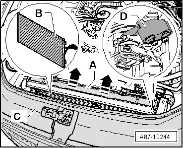
- Remove the noise insulation.
- Move the lock carrier - C - into the service position (for example, on a 12-cylinder TDI engine). Radiator Support
- Release the tension on the ribbed belt and remove it.
• Belt pulley is made of plastic and is sensitive to impact. Be careful when handling it.
• If overload safeguard of drive plate - C - has triggered, drive plate can be pried off from belt pulley - D - after removing circlip - A -
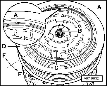
• Depending on production time period, drive plates with 3 holes (as shown) or one outer hex head on the front side are installed.
• A plastic disc - B - may be glued on or a circlip with a rubber disc vulcanized onto it may be installed on the belt pulley drive plate - A - to optimize noise reduction, refer to the Electronic Parts Catalog. This plastic or the rubber disc - B - can produce a clapping (castanet-like) noise which occurs especially on diesel vehicles when the A/C compressor is off (for example, when ECON is on). The noise is almost inaudible when the A/C system is operating at full output.
• Versions having the drive plate outer hex head (instead of holes) with a circlip but without a rubber disc are still being installed until further notice.
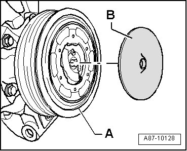
Belt Pulley, Removing
- Remove plastic disc - B - from belt pulley - A - (if installed).
- Using for example, a small screwdriver or needle-nose pliers, carefully remove circlip - A - (which might have rubber disc vulcanized on to it); take extreme care not to damage belt pulley when doing this.
- Hold compressor driveshaft - B - firmly in place using a socket or socket wrench (T10001/10) from shock absorber set (depending on version of compressor) and rotate drive plate - C - along with belt pulley - D - in direction of arrow - E - (tightening torque 35 Nm).
• Depending on production time period, drive plates with 3 holes (as shown) or one outer hex head on the front side are installed.
- Remove circlip - A -.
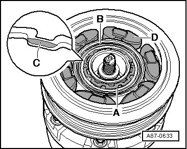
- Remove pulley - B -.
Belt Pulley, Installing
• Replace circlip - A -.
• Clean compressor flange before sliding on belt pulley.
• When installing the circlip - A -, note that it cannot be bent open more than is necessary for installation.
- Install belt pulley - B -.
- Insert circlip - A - on proper side, the side with beveled insertion edge - C - faces away from compressor (install flat side facing compressor).
- Insert rubber element - D - in belt pulley - B - according to illustration.
- When installing drive plate, coat rubber element - D - lightly for example, with tire mounting paste or soap solution (as sliding compound).
- Insert drive plate - C - far enough into rubber elements - D - until it contacts compressor shaft - B -.
- Screw drive plate - C - onto compressor shaft - B - by rotating in direction of arrow - F -.
- Tighten drive plate - C - to 35 Nm by rotating using a conventional band wrench (with webbed band) or a hex socket wrench (depending on version) in direction of arrow - E -, counter-hold compressor shaft - A - using a retainer - B - (for example, using a socket or socket wrench (T10001/10) from socket wrench set) on compressor shaft - A -.
- Install circlip - A -.
- Clean drive plate of belt pulley - A - and glue plastic disc - B - centered onto drive plate (only on A/C compressors with 3 holes in the drive plate and without rubber disc on the circlip).
• Depending on production time period, drive plates - A - with 3 holes (as shown) or one outer hex head on the front side are installed. If necessary, install a plastic disc - B - on version with 3 holes (not intended at this time on version with outer hex head).
• As of MY 07, circlips that have a rubber disc vulcanized on to them are installed as a running change, do not glue plastic disc on to these compressors.