Procedures
Lock Carrier, Service Position
Special tools, testers and auxiliary items required
• Guide Rods (T10093)
• For service position, do not disconnect any electrical wires or circuits for, for example, engine cooling, A/C system, etc.
• When installing lock carrier, ensure no lines are cables are pinched or kinked at securing points.
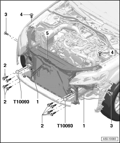
1 Bolt
• 6 Nm
• Do not remove for service position.
2 Bolt
• Guide Pins (T10093) are installed in free threads at outer left and right.
• 60 Nm
3 Bolt
• 3 Nm
4 Bolt
• 25 Nm
5 Lock Carrier
• Service Position
- Remove the front bumper. Refer to => [ Front Bumper ] Front Bumper.
- Loosen wheel housing in area of bolting point to bumper. Refer to=> [ Front Wheel Housing Liners ] Service and Repair.
- Remove screws on lower noise insulation. Refer to => [ Noise Insulation Overview ] Noise Insulation Overview.
- Remove seal on lock carrier and transition to fender. Refer to=> [ Hood Seal ] Service and Repair.
- Remove the headlamp.
- Disconnect release at connector station. Refer to => [ Cable Coupling ] Overview of Connector Stations.
- On vehicles with charge air cooler, pressure hoses must also be disconnected.
- Remove bolts - 4 - and - 3 -.
- Remove upper right or left screws - 2 - from longitudinal member.
- Install the (T10093) into the thread, which is now open.
- Remove remaining screws - 2 -.
- Remove lock carrier without stretching wires forward on guide pins.
When removing lock carrier, wiring must not be pinched or kinked.
• Adjust headlamps after installing.