Intake Manifold Assembly Overview
Intake Manifold Assembly Overview
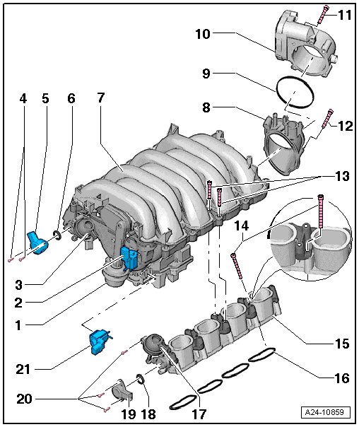
1 Intake Manifold Change-Over Valve Vacuum Diaphragm
2 Intake Manifold Tuning Valve (N156)
3 Intake Flap Vacuum Diaphragm (cylinder bank 1)
• For cylinder bank 1 CVTS tumble flaps
4 Bolt
• 2.5 Nm
5 Intake Manifold Runner Position Sensor (G336)
• Cylinder Bank 1
• Perform an adaptation with the vehicle diagnosis tester guided functions after replacing.
6 Gasket
• Replace if damaged
• The open side faces the potentiometer
7 Intake Manifold
• Removing and installing, refer to => [ Intake Manifold ] Intake Manifold
8 Intermediate Flange
9 O-ring
• Replace
10 Throttle Valve Control Module (J338)
• Removing and installing, refer to => [ Throttle Valve Control Module ] Throttle Valve Control Module
• Perform an adaptation with the vehicle diagnosis tester guided functions after replacing.
11 Bolt
• 9 Nm
12 Bolt
• 9 Nm
13 Intake Manifold Bolts
• Tightening specification and sequence
14 Intake Manifold Lower Section Bolts
• Tightening specification and sequence
15 Intake Manifold Lower Section
16 Gasket for Intake Manifold
• Replace
17 Intake Flap Vacuum Diaphragm (cylinder bank 2)
• For cylinder bank 2 CVTS tumble flaps
18 Gasket
• Replace if damaged
• The open side faces the potentiometer
19 Intake Manifold Runner Position Sensor 2 (G512)
• Cylinder Bank 2
• Perform an adaptation with the vehicle diagnosis tester guided functions after replacing.
20 Bolt
• 2.5 Nm
21 Intake Manifold Runner Control Valve (N316)
Intake Manifold, Tightening Specification and Sequence
- Tighten intake manifold bolts in - 1 through 16 - sequence.
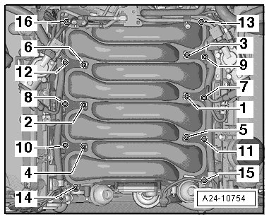
• First tightening: 8 Nm
• Second tightening: 11 Nm
Tightening Specification, Intake Manifold Lower Section
- Tighten the bolts - arrows - for the intake manifold lower section diagonally and in steps.
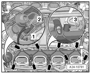
• 10 Nm