3.0L CGXB Overview
Component Locations: Engine Management System
3.0L CGXB Overview
Engine Compartment, Right
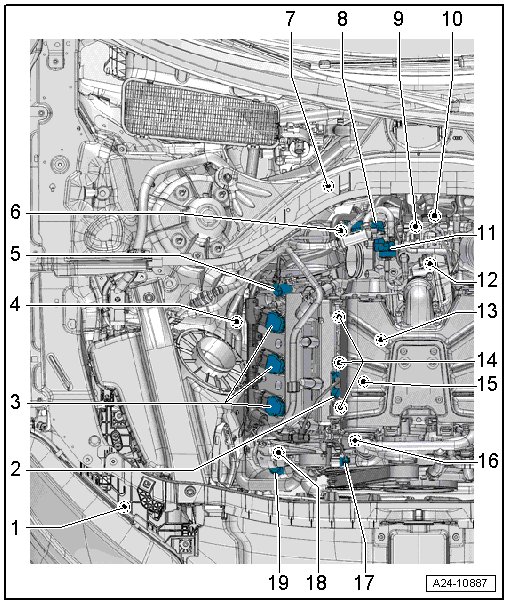
1 Secondary Air Pump Motor -V101-
• Installed location, refer to => See Image Below.
2 Charge Air Pressure Sensor -G31- / Intake Manifold Temperature Sensor -G72-
• Installed location, refer to => [ Installation Location / ] See Image Below.
3 Ignition Coils, Cylinder Bank 1
• Ignition coil 1 with power output stage -N70-
• Ignition coil 2 with power output stage -N127-
• Ignition coil 3 with power output stage -N291-
4 Heated Oxygen Sensor (HO2S) -G39-
• With oxygen sensor heater -Z19-
• Installed location, refer to => [ Oxygen Sensor Locations, Cylinder Bank 1 (right) ] Locations
5 Camshaft Adjustment Valve 1 -N205-
• Installed location, refer to => [ Camshaft Position Sensor and Exhaust Camshaft Control Valve Cylinder Bank 1 (right) ] See Image Below.
6 Electrical Connectors
• Connector assignment, refer to => [ Electrical Connectors on Left Rear of Engine ] See Image Below.
7 Oxygen Sensor (O2S) after Three Way Catalytic Converter (TWC) -G130-
• With heater for oxygen sensor 1 after catalytic converter -Z29-
• Installed location, refer to => [ Oxygen Sensor Locations, Cylinder Bank 1 (right) ] Locations
• Connector location, refer to => [ Electrical Connectors on Right Rear of Engine ] See Image Below.
8 Throttle Valve Control Module -J338-
• Installed location, refer to => See Image Below.
9 Intake Air Temperature (IAT) Sensor -G42- /Manifold Absolute Pressure (MAP) Sensor -G71-
• Installed location, refer to => [ / ] See Image Below.
10 Secondary Air Injection (AIR) Sensor 1 -G609-
• Installed location, refer to => See Image Below.
11 Evaporative Emission (EVAP) Canister Purge Regulator Valve 1 -N80- => [ EVAP system routing ] Locations
12 Engine Speed (RPM) Sensor -G28-
• Installed location, refer to => See Image Below.
13 Knock Sensor (KS) 1 -G61-
• Installed location, refer to => [ Component Location Under the Intake Manifold Lower Section, Cylinder Bank 1 (right) ] See Image Below.
• Connector location, refer to => [ Electrical Connectors on Right Rear of Engine ] See Image Below.
14 Fuel Injectors, Cylinder Bank 1
• Cylinder 1 fuel injector -N30-
• Cylinder 2 fuel injector -N31-
• Cylinder 3 fuel injector -N32-
15 Engine Temperature Control Temperature Sensor -G694-
• Installed location, refer to => See Image Below.
16 Intake Manifold Runner Position Sensor -G336-
• Installed location, refer to => See Image Below.
17 Camshaft Position (CMP) Sensor -G40-
• Installed location, refer to => [ Camshaft Position Sensor and Exhaust Camshaft Control Valve Cylinder Bank 1 (right) ] See Image Below.
18 Fuel Metering Valve -N290-
• Installed location, refer to => [ High Pressure Pump ] See Image Below.
19 Low Fuel Pressure Sensor -G410-
• Installed location, refer to => [ High Pressure Pump ] See Image Below.
Engine Compartment, Left
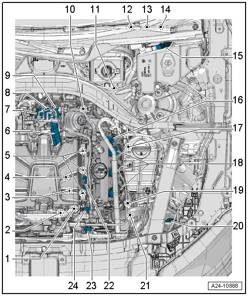
1 Intake Manifold Runner Position Sensor 2 -G512-
• Installed location, refer to => See Image Below.
2 Engine Coolant Temperature Sensor -G62-
• Installed location, refer to => See Image Below.
3 Fuel Pressure Sensor -G247-
• Installed location, refer to => [ Component Location under the Intake Manifold Lower Section, Cylinder Bank 2 (left) ] See Image Below.
4 Knock Sensor (KS) 2 -G66-
• Installed location, refer to => [ Component Location under the Intake Manifold Lower Section, Cylinder Bank 2 (left) ] See Image Below.
• Connector location, refer to => [ Electrical Connectors on Left Rear of Engine ] See Image Below.
5 Fuel Injectors, Cylinder Bank 2
• Cylinder 4 fuel injector -N33-
• Cylinder 5 fuel injector -N83-
• Cylinder 6 fuel injector -N84-
6 Control Valve Control Unit -J808-
• Installed location, refer to => See Image Below.
7 Secondary Air Injection Solenoid Valve -N112-
• Installed location, refer to => [ Secondary Air Injection Solenoid Valve and ] See Image Below.
8 Intake Manifold Runner Control Valve -N316-
• Installed location, refer to => [ Secondary Air Injection Solenoid Valve and ] See Image Below.
9 Secondary Air Injection Solenoid Valve 2 -N320-
• Installed location, refer to => [ Secondary Air Injection Solenoid Valve and ] See Image Below.
10 Electrical Connectors
• Connector assignment, refer to => [ Electrical Connectors on Left Rear of Engine ] See Image Below.
11 Oxygen Sensor 2 after Catalytic Converter -G131-
• With heater for oxygen sensor 2 after catalytic converter -Z30-
• Installed location, refer to => [ Oxygen Sensor Locations, Cylinder Bank 2 (left) ] Locations
• Connector location, refer to => [ Electrical Connectors on Left Rear of Engine ] See Image Below.
12 Engine Malfunction Lamp
• Inside the instrument cluster
13 Accelerator Pedal Position Sensor -G79- /Accelerator Pedal Position Sensor 2 -G185-
• In accelerator pedal module, component location, refer to => [ / ] Locations
14 Brake Lamp Switch -F- /Brake Pedal Switch -F47-
• Installed location, refer to => [ Installed Location / ] Locations
15 Engine Control Module (ECM) -J623-
• Installed location, refer to => See Image Below.
16 Camshaft Adjustment Valve 2 -N208-
Installed location, refer to => [ Camshaft Position Sensor and
Exhaust Camshaft Control Valve Cylinder Bank 2 (left) ] See Image Below.
17 Heated Oxygen Sensor (HO2S) 2 -G108-
• With oxygen sensor (O2S) 2 heater -Z28-
• Installed location, refer to => [ Oxygen Sensor Locations, Cylinder Bank 2 (left) ] Locations
• Connector location, refer to => [ Electrical Connectors on Left Rear of Engine ] See Image Below.
18 Ignition Coils, Cylinder Bank 2
• Ignition coil 4 with power output stage -N292-
• Ignition coil 5 with power output stage -N323-
• Ignition coil 6 with power output stage -N324-
19 Oil Pressure Regulation Valve -N428-
• Installed location, refer to => See Image Below.
20 Charge Air Coolant Pump -V188-
• Installed location, refer to => See Image Below.
21 After-Run Coolant Pump -V51-
• Depending on the vehicle equipment level or the country
• Installed location, refer to => See Image Below.
22 Intake Air Temperature Temperature Sensor 2 -G430- /Charge Air Pressure Sensor 2 -G447-
• Installed location, refer to => [ Installation Location / ] See Image Below.
23 Cylinder Head Coolant Valve -N489-
24 Camshaft Position Sensor 2 -G163-
• Installed location, refer to => [ Camshaft Position Sensor and Exhaust Camshaft Control Valve Cylinder Bank 2 (left) ] See Image Below.
Engine Control Module (ECM) -J623-
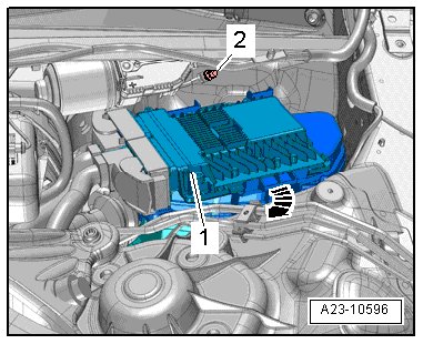
1 - inside the plenum chamber on the left side.
Electrical Connectors on Right
Rear of Engine
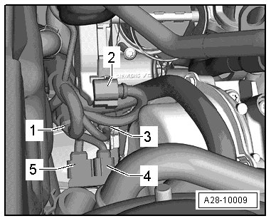
1 - For cylinder bank 1 fuel injectors
2 - For the throttle valve control module -J338-
3 - For Knock Sensor (KS) 1 -G61-
4 - For the Heated Oxygen Sensor (HO2S) -G39- with Oxygen Sensor (O2S) Heater -Z19-
5 - For oxygen sensor (O2S) after three way catalytic converter (TWC) -G130- with heater for oxygen sensor 1 after catalytic converter -Z29-
Electrical Connectors on Left
Rear of Engine
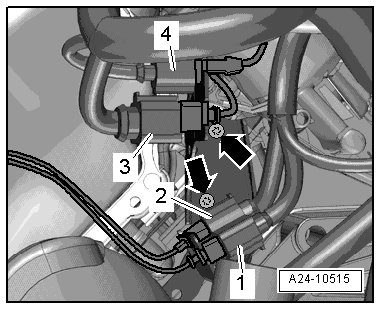
1 - For oxygen sensor (O2S) 2 behind three way catalytic converter (TWC) -G131- with heater for oxygen sensor 2 after catalytic converter -Z30-
2 - ated oxygen sensor (HO2S) 2 -G108- with oxygen sensor 2 heater -Z28-
3 - For cylinder bank 2 fuel injectors and fuel pressure sensor -G247-
4 - To Knock Sensor (KS) 2 -G66-
High Pressure Pump
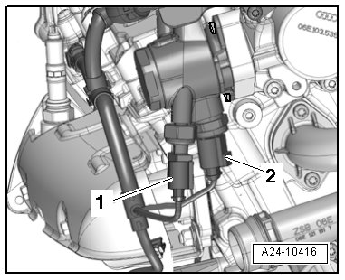
• At right side of the cylinder head
1 - Low Fuel Pressure Sensor -G410-
2 - ing Valve -N290-
Component Location Under the
Intake Manifold Lower Section, Cylinder Bank 1 (right)
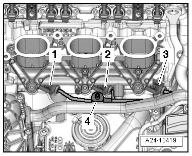
1 - Cylinder 1 fuel injector -N30-
2 - Cylinder 2 fuel injector -N31-
3 - Cylinder 3 fuel injector -N32-
4 - Knock sensor (KS) 1 -G61-
Engine Temperature Control Temperature Sensor -G694-
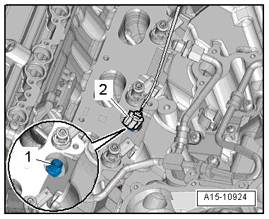
• -1- under the intake manifold lower section, cylinder
bank 1 (right side)
Component Location under the
Intake Manifold Lower Section, Cylinder Bank 2 (left)
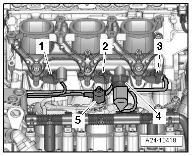
1 - Cylinder 6 fuel injector -N84-
2 - Cylinder 5 fuel injector -N83-
3 - Cylinder 4 fuel injector -N33-
4 - Fuel pressure sensor -G247-
5 - Knock sensor (KS) 2 -G66-
Throttle Valve Control Module -J338-
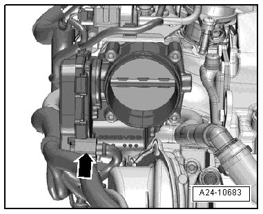
• Behind, on the supercharger
Control Valve Control Module -J808-
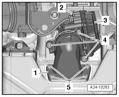
• -3- on the back of the supercharger.
Intake Manifold Runner Position Sensor -G336-
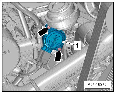
• -1- at the front, on the right side of the intake
manifold lower section
Note:
• Intake manifold runner position sensor 2 -G512- is installed as a mirror image.
Intake Air Temperature Sensor -G42- /Manifold Absolute Pressure Sensor -G71-
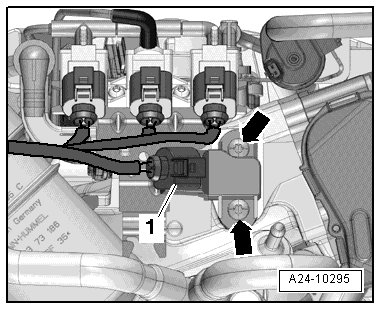
• Behind, on the supercharger with the charge air cooler.
1 - Connector for intake air temperature sensor -G42- /manifold absolute pressure sensor -G71-
Installation Location Charge Air Pressure Sensor -G31- /Intake Manifold Temperature Sensor -G72-
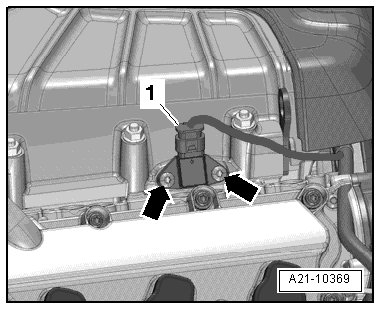
• On the right side, on the supercharger with the charge air cooler.
1 - Connector for charge air pressure sensor -G31- /intake manifold temperature sensor -G72-
Note:
• The intake air temperature sensor 2 -G430- / charge air pressure sensor 2 -G447- are arranged as
mirror image of each other.
Camshaft Position Sensor and
Exhaust Camshaft Control Valve Cylinder Bank 1 (right)
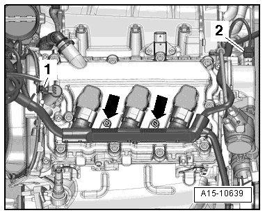
1 - Camshaft adjustment valve 1 -N205-
2 - Camshaft position sensor -G40-
Camshaft Position Sensor and
Exhaust Camshaft Control Valve Cylinder Bank 2 (left)
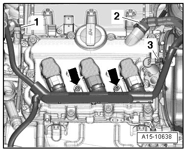
1 - Camshaft position sensor (CMP) 2 -G163-
2 - Camshaft adjustment valve 2 -N208-
Oil Pressure Regulation Valve -N428-
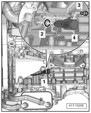
• -4- on the left side at the bottom of the engine.
Engine Coolant Temperature (ECT) Sensor -G62-
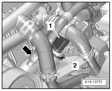
• At front on engine
1 - Connector for engine coolant temperature (ECT) sensor -G62-
Charge Air Cooling Pump -V188-
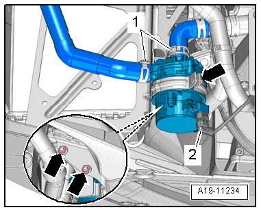
• Inside the left front wheel housing
2 - Charge air cooling pump -V188- connector
After-Run Coolant Pump -V51-
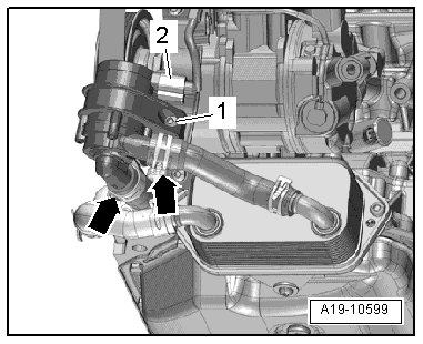
• Left side, at the front, on the engine
2 - After-run coolant pump -V51- connector
Engine Speed (RPM) Sensor -G28-
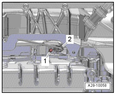
• At the bottom of the timing chain guard lower section
2 - Engine speed (RPM) sensor -G28- connector
Secondary Air Injection Solenoid
Valve and Intake Manifold Runner Control Valve -N316-
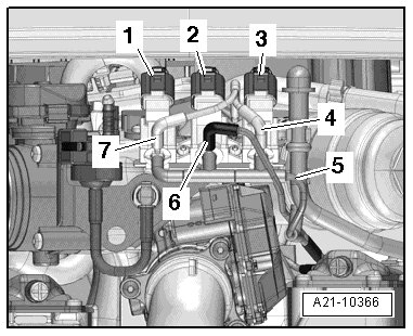
• Behind, on the supercharger with the charge air cooler.
1 - Secondary air injection solenoid valve -N112-
2 - Intake manifold runner control valve -N316-
3 - Secondary air injection solenoid valve 2 -N320-
Secondary Air Pump Motor -V101-
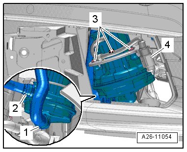
• Inside the right front wheel housing.
4 - Secondary air injection pump motor -V101- connector
Secondary Air Injection Sensor 1 -G609-
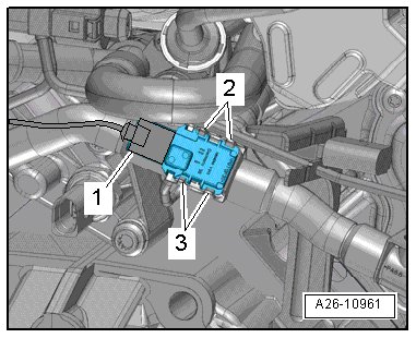
• On the back of the engine.
1 - Secondary air injection sensor 1 -G609- connector