Fuel Delivery, Checking
Fuel Delivery, Checking
Special tools, testers and auxiliary items required
• Hand held remote control (jumper).
• Multimeter.
• Fuel pressure test set (high pressure).
• Measuring container, fuel-resistant.
Test conditions
• Battery voltage min. 12.5 V.
• Fuel filter OK.
• Fuse (SB81) OK.
• Fuel Pump (FP) Control Module (J538) OK.
• Fuel tank at least 1/4 filled.
• Ignition switched off.
• Observe all safety precautions. Refer to => [ Safety Precautions ] Fuel Supply.
• Observe all clean working conditions. Refer to => [ Clean Working Conditions ] General, Technical Data.
Work procedure
- Slide the seats forward as far as possible. Then fold seat back forward.
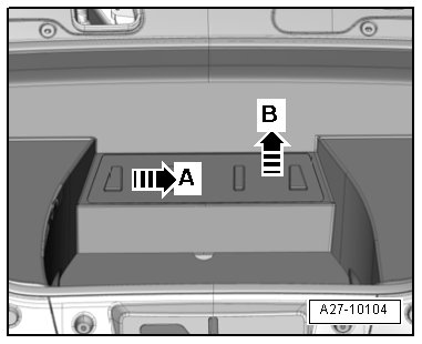
- Push the battery cover to the side - arrow A - and lift upward - arrow B -.
- Loosen the negative battery cable terminal nut - 1 - and remove the cable from the battery negative post.
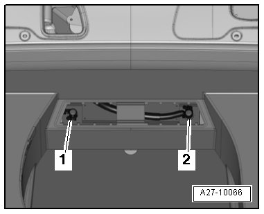
- Loosen the positive battery cable terminal nut - 2 - and remove the cable from the battery positive post.
- Remove the rear shelf.
- Remove the side trim panel.
- Remove the positive wire - 4 -.
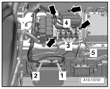
- Disconnect the electrical connector station electrical connectors - 3 - and remove the connector station from the control module bracket and lay it to the side.
- Remove the right rear relay and fuse carrier from the control module bracket and lay it aside - arrows -.
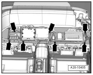
- Disconnect the engine control module electrical connectors and remove the engine control module bracket - arrow - from vehicle.
- Using a pry bar, remove the electrical wiring harness from the rear bulkhead.
- Fold the insulation mat up to gain access to the locking flange cover.
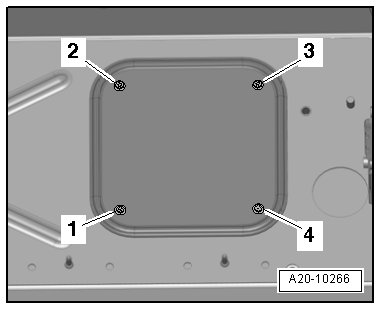
- Remove the right locking flange bolts - 1 through 4 - and remove the right locking flange cover.
- Disconnect the electrical connector - arrow - from the right locking flange.
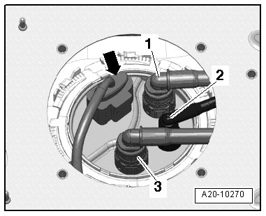
- Connect a Hand held remote control (jumper) to the right locking flange electrical terminal - 1 -.
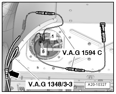
- Connect a Hand held remote control (jumper) to the right locking flange electrical terminal - 5 -.
- Press the Hand held remote control (jumper) button in to run the fuel pump.
- Remove the fuel filler tube cover.
- Install he protective body covers.
• A second technician must hold the lid securely while the rear lid gas-filled strut - 3 - is disengaged from the lower left joints.
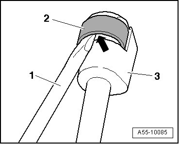
- Using a small screwdriver - 1 -, release the retaining spring - 2 - - arrow - and remove the gas-filled strut from the ball stud.
- Remove the power steering reservoir cap on left engine compartment trim.
- Loosen the quick-release fasteners and remove the left engine compartment trim - 1 -.
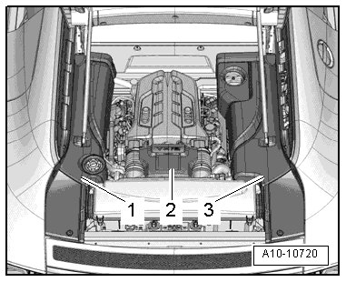
- Install the gas-filled strut back onto ball studs.
Risk of injury from fuel.
• To reduce pressure in fuel system, lay a clean cloth around the connector and carefully loosen connector.
- Disconnect the fuel supply line - arrow -.
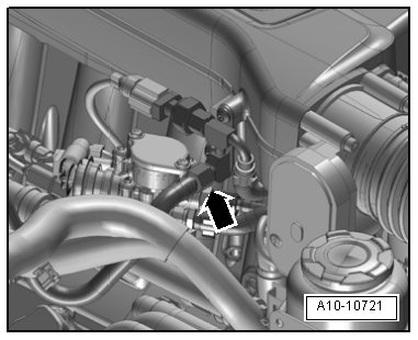
- Connect a Fuel pressure test set (high pressure) to the fuel supply line.
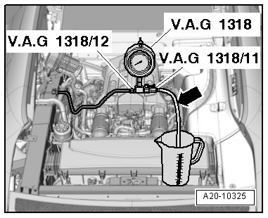
- Connect an assisting hose - arrow - on the Fuel pressure test set (high pressure) and hold in a measuring container.
- Open the pressure gauge shut-off valve.
- Operate Hand held remote control (jumper) to run the fuel pump and slowly close the shut-off valve.
Specified value: 4 bar positive pressure.
- From this point on do not move position of shut-off valve.
- Empty the measuring container.
- Operate Hand held remote control (jumper) to run the fuel pump for 15 seconds.
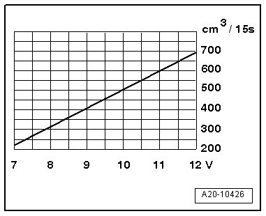
- Compare the quantity of fuel delivered with minimum delivery rate in diagram (cm3/15 s).
• Voltage at fuel pump with engine stopped and pump running is approximate. 2 volts less than battery voltage.
If the minimum delivery quantity is not obtained, check for the following:
• Pinched fuel lines.
• Clogged fuel filter.
• Faulty fuel pump.
Assembly is performed in the reverse order of the removal, note the following:
Final procedures
After repair work, the following work steps must be performed in the following sequence:
1. Check the DTC memory. Refer to => [ Diagnostic Mode 03 - Read DTC Memory ] Diagnostic Mode 03 - Read DTC Memory.
2. If necessary, erase the DTC memory. Refer to => [ Diagnostic Mode 04 - Erase DTC Memory ] Clearing Diagnostic Trouble Codes.
3. If the DTC memory was erased, generate readiness code. Refer to => [ Readiness Code ] Readiness Code.