Component Locations Overview
Component Locations Overview
Components A through I are not depicted in the exploded view illustration.
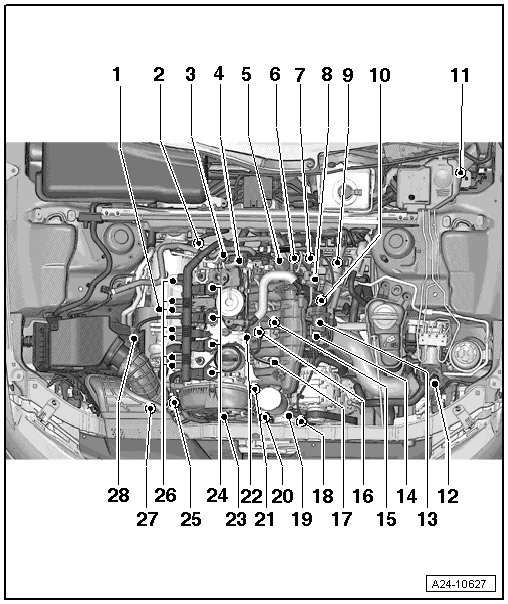
1 - Heated Oxygen Sensor (HO2S) (G39) and Oxygen Sensor (O2S) Heater (Z19)
• Removing and installing, refer to => [ Heated Oxygen Sensor (G39) and Oxygen Sensor Heater (Z19) ] Heated Oxygen Sensor (G39) and Oxygen Sensor Heater (Z19)
2 - Oxygen Sensor (O2S) after Three Way Catalytic Converter (TWC) (G130) and Heater for Oxygen Sensor (O2S) 1 after Catalytic Converter (Z29)
• Removing and installing, refer to => [ Oxygen Sensor after Three Way Catalytic Converter (G130) and Heater for Oxygen Sensor 1 after Catalytic Converter (Z29) ] Oxygen Sensor After Three Way Catalytic Converter (G130) and Heater For Oxygen Sensor 1 After Catalytic Converter (Z29)
3 - Fuel Pressure Regulator Valve (N276)
4 - High Pressure Pump
5 - Channel Separating Plate Vacuum Diaphragm (intake manifold flaps)
6 - Intake Manifold Runner Control (IMRC) Valve (N316)
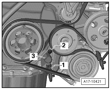
7 - Engine Speed (RPM) Sensor (G28)
• 4.5 Nm
8 - Evaporative Emission (EVAP) Canister Purge Regulator Valve 1 (N80)
9 - 6-Pin Connectors
• For Heated Oxygen Sensor (HO2S) (G39) and Oxygen Sensor (O2S) Heater (Z19) (black)
• Oxygen Sensor (O2S) after Three Way Catalytic Converter (TWC) (G130) and Heater for Oxygen Sensor (O2S) 1 after Catalytic Converter (Z29) (brown connector)
10 - Connectors
• For Knock Sensor (KS) 1 (G61) , IMRC valve, fuel pressure sensor (G247) , intake manifold runner position sensor (G336) , Engine Coolant Temperature (ECT) sensor (G62) , Camshaft Position (CMP) sensor (G40) and fuel injectors N30...N33
11 - Engine Control Module (ECM) (J623)
• Removing and installing, refer to => [ Engine Control Module (J623) ] Service and Repair
12 - Charge Air Pressure Sensor (G31)
13 - Throttle Valve Control Module (J338), Electronic Power Control (EPC) throttle drive (G186)
• EPC throttle drive angle sensor 1 (G187) and EPC throttle drive angle sensor 2 (G188)
• Each time the throttle valve control module is removed and installed or replaced, it must be adapted to the ECM.
14 - Intake Air Temperature (IAT) Sensor (G42)
15 - Knock Sensor (KS) 1 (G61)
• 20 Nm
• In order to remove, the coolant pump and coolant thermostat must be removed
• Removing and installing, refer to => [ Knock Sensor 1 (G61) ] Service and Repair
16 - Engine Coolant Temperature (ECT) Sensor (G62)
17 - Fuel Pressure Sensor (G247)
• Removing and installing, refer to => [ Fuel Pressure Sensor (G247) ] Service and Repair
18 - Oil Pressure Regulation Valve (N428)
19 - Reduced Oil Pressure Switch (F378)
20 - Oil Pressure Switch (F22)
21 - Intake Manifold Runner Position Sensor (G336)
22 - Camshaft Position (CMP) Sensor (G40)
23 - Camshaft Adjustment Valve 1 (N205)
24 - Ignition Coils with Power Output Stages
• The ignition coils must be pulled out of the cylinder head using the ignition coil puller (T40039)
• Removing and installing, refer to => [ Ignition Coils with Power Output Stages ] Ignition Coils With Power Output Stages
25 - Turbocharger Recirculating Valve (N249)
26 - Cam Adjustment Actuator
• Cam adjustment actuator 1 (F366)
• Cam adjustment actuator 2 (F367)
• Cam adjustment actuator 3 (F368)
• Cam adjustment actuator 4 (F369)
• Cam adjustment actuator 5 (F370)
• Cam adjustment actuator 6 (F371)
• Cam adjustment actuator 7 (F372)
• Cam adjustment actuator 8 (F373)
27 - Wastegate Bypass Regulator Valve (N75)
28 - Mass Airflow (MAF) Sensor (G70)
• Removing and installing, refer to => [ Mass Airflow Sensor (G70) ] Mass Airflow Sensor (G70)
A - Data Link Connector (DLC)
• In knee bolster on driver's side
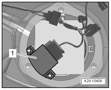
B - Fuel Pump (FP) Control Module (J538)
C - Brake Lamp Switch (F) and Brake Pedal Switch (F47)
• In footwell at brake pedal
D - Clutch Position Sensor (G476)
• Only on vehicles with a manual transmission
E - Accelerator Pedal Position Sensor (G79) and Accelerator Pedal Position Sensor 2 (G185)
• On accelerator pedal (both sensors are stored in one housing
F - Coolant Fan Control Module (J293)
• Installed inside the coolant fan
G - Fuel Injectors
• Cylinder 1 fuel Injector (N30)
• Cylinder 2 fuel Injector (N31)
• Cylinder 3 fuel Injector (N32)
• Cylinder 4 fuel Injector (N33)
• Removing and installing, refer to => [ Fuel Injectors ] Fuel Injectors
H - After-Run Coolant Pump (V51)
• Not installed on all vehicles (only extreme hot climate countries)
I - Left Electrohydraulic Engine Mount Solenoid Valve (N144)
• Not installed in all vehicles (depends on the transmission)
Engine Control Module (ECM) (J623)
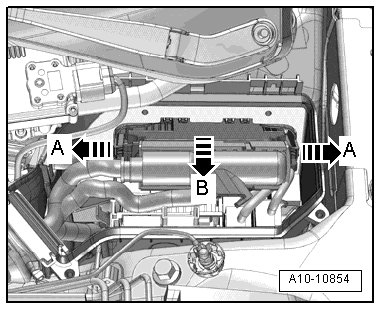
• Inside the left E-box in the engine compartment.
FP Control Module - 1 -
Accelerator Pedal Position Sensor and Accelerator Pedal Position Sensor 2
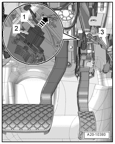
2 Connector
Clutch Position Sensor - 2 -
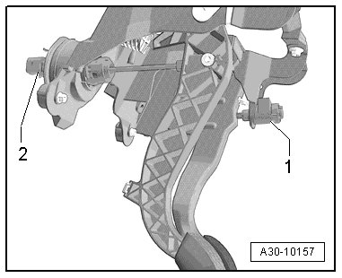
Integrated functions: clutch pedal starter interlock switch (F194) and clutch pedal switch (F36) (manual transmission only)
1 Brake lamp switch and brake pedal switch
After-Run Coolant Pump
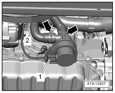
1 After-run coolant pump connector
Oil Pressure Switch
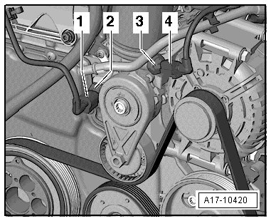
1 Oil pressure switch connector
2 Oil pressure switch
3 Reduced oil pressure switch
4 Reduced oil pressure switch connector
Oil Pressure Regulation Valve - 3 -
Ignition Coils
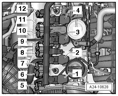
1 Ignition coil 1 with power output stage (N70)
2 Ignition coil 2 with power output stage (N127)
3 Ignition coil 3 with power output stage (N291)
4 Ignition coil 4 with power output stage (N292)
5 Cam adjustment actuator 2 (F367) (for cylinder 1)
6 Cam adjustment actuator 1 (F366) (for cylinder 1)
7 Cam adjustment actuator 3 (F368) (for cylinder 2)
8 Cam adjustment actuator 4 (F369) (for cylinder 2)
9 Cam adjustment actuator 6 (F371) (for cylinder 3)
10 Cam adjustment actuator 5 (F370) (for cylinder 3)
11 Cam adjustment actuator 7 (F372) (for cylinder 4)
12 Cam adjustment actuator 8 (F373) (for cylinder 4)
Fuel Pressure Sensor - 1 -
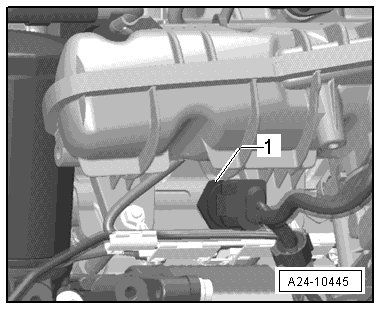
IMRC Valve - 2 -
1 Intake manifold flap vacuum diaphragm
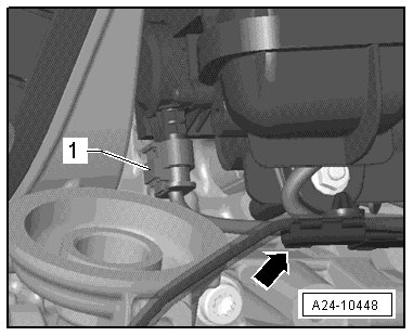
Intake Manifold Runner Position Sensor - 1 -
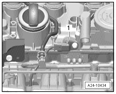
CMP Sensor - 1 -
Connectors
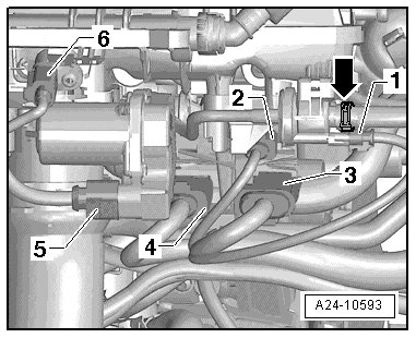
1 From EVAP canister purge regulator valve 1
2 From the KS 1
3 (14-pin) intake manifold runner control valve, fuel pressure sensor, intake manifold runner position sensor, ECT Sensor and CMP Sensor
4 (8-pin) from fuel injectors N30 to N33
5 From the throttle valve control module
6 IAT sensor
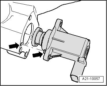
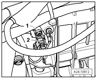
High Pressure Pump
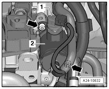
1 Fuel pressure regulator valve
2 High pressure pump
- arrows - bolts
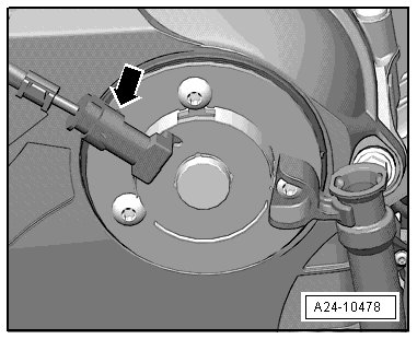
RPM Sensor - 2 -
Camshaft Adjustment Valve 1 - arrow -
Components
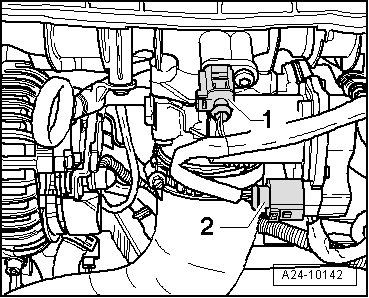
1 IAT sensor
2 Throttle valve control module
ECT sensor - 1 -
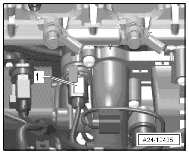
Installed below from the intake manifold inside the coolant pump.
Charge Air Pressure Sensor - 1 -
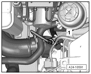
Component and Connectors
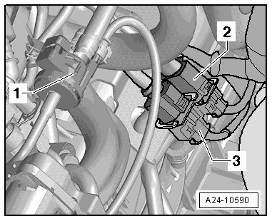
1 EVAP canister purge regulator valve 1 (N80)
2 Oxygen Sensor (O2S) after Three Way Catalytic Converter (TWC) (G130) and Heater for Oxygen Sensor (O2S) 1 after Catalytic Converter (Z29)
3 Heated Oxygen Sensor (HO2S) (G39) and Oxygen Sensor (O2S) Heater (Z19)
Oxygen Sensors
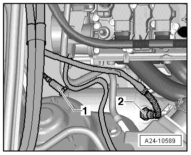
1 Oxygen Sensor (O2S) after Three Way Catalytic Converter (TWC) (G130) and Heater for Oxygen Sensor (O2S) 1 after Catalytic Converter (Z29)
2 Heated Oxygen Sensor (HO2S) (G39) and Oxygen Sensor (O2S) Heater (Z19)
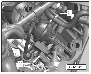
Components on Turbocharger
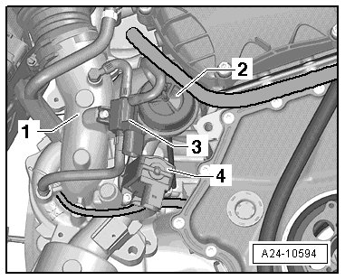
1 Turbocharger
2 Turbocharger vacuum diaphragm
3 Wastegate bypass regulator valve
4 Turbocharger recalculating valve (note the installation position, next illustration)
Observe Installed Location of Turbocharger Recirculating Valve