Vehicle Speed Sensor: Testing and Inspection
Diagnostic Procedures
Speed Signal, Checking
Special tools, testers and auxiliary items required
• Hand multimeter (V.A.G 1526) or Multimeter (V.A.G 1715)
• Test adapter kit (V.A.G 1594)
• Wiring diagram
Test Conditions
• Motronic Engine Control Module (ECM) Power Supply Relay must be OK, checking:
• Motronic Engine Control Module (ECM) Power Supply Relay 2 must be OK, checking:
• Instrument Cluster Control Module (J285) must be OK.
• Battery voltage (both batteries) must be at least 11.5 Volts.
• The fuses must be OK:
Right instrument panel fuse holder
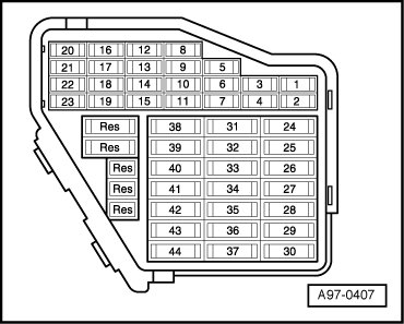
Test Sequence
Function test
• To check the speed signal, vehicle must be driven at a speed above 5 km/h.
Observe safety precautions that apply to road tests, refer to Repair Manual.
- Connect diagnostic tester.
- Start engine and let run at idle.
- Under address word 33, select "Diagnostic mode 1: Check measured values".
- Select measured value "PID 13: Vehicle speed".
- Perform a road test at a speed above 5 km/h and have a second person observe the indication on the display.
- Check specified value of the vehicle speed:

• Vehicle speed must not drop to below 5 km/h during test.
- End road test and switch ignition off.
If no speed is displayed:
- Check Data-Bus wiring according to wiring diagram.
Checking wiring
- Connect test box to wiring harness on corresponding Engine Control Module at connecting test box for wiring test, refer to Repair Manual,
- Remove instrument cluster, refer to Repair Manual
- Repair malfunction in CAN-Bus wires between both Engine Control Modules and (J285)Instrument Cluster Control Module (J285) according to wiring diagram:
- Erase DTC memory of Engine Control Module => [ Diagnostic Mode 04 - Erase DTC Memory ] Diagnostic Modes 01 - 09, Diagnostic mode 4: Reset/erase diagnostic data.
- Generate readiness code => [ Readiness Code, Generating ] Monitors, Trips, Drive Cycles and Readiness Codes.