Coolant Temperature Sensor, Checking
Diagnostic Procedures
Coolant Temperature Sensor, Checking
• Use only gold-plated terminals when servicing terminals in harness connector of sensor.
Special tools, testers and auxiliary items required
• Hand multimeter (V.A.G 1526) or Multimeter (V.A.G 1715)
• Test adapter kit (V.A.G 1594)
• Wiring diagram
Test conditions
• For vehicles with automatic transmission, selector lever must be in " P".
• Parking brake must be engaged.
• The Ground (GND) connections between engine and body must be OK.
• Engine must be cold.
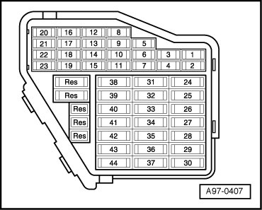
• Fuses in right instrument panel fuse holder must be OK:
Right instrument panel fuse holder
Function Test
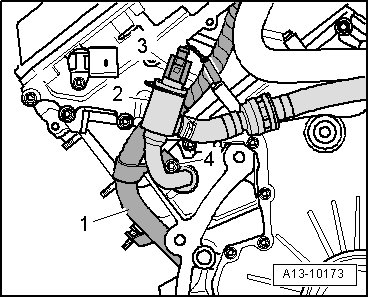
Component location: Between engine and bulkhead
- Connect diagnostic tester.
- Switch ignition on.
- Under address word 33, select "Diagnostic mode 1: Check measured values".
- Select measured value "PID 05: Coolant temperature".
- Check specified value of coolant temperature:

If specification is not obtained:
- Perform test according to the following table:

* If a temperature is display that deviates strongly from the sensor ambient temperature, check sensor wires for contact resistance.
If specification is obtained:
- Start engine and run at idle speed. The temperature value must increase steadily
• The temperature increases in increments of 1.0 °C
• If the engine shows problems in certain temperature ranges and the temperature does not climb uniformly, the temperature signal is intermittent and the sensor must be replaced.
- End diagnosis and switch ignition off.
°Continuation of Test If Indication is Approx. -40 C:
- Remove 2-pin connector - 3 - from Engine Coolant Temperature (ECT) Sensor (G62).
Engine Coolant Temperature (ECT) Sensor
- Bridge terminals 1 + 2 of connector using respective adapter cables and observe the indication on display.
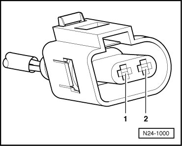
If indication jumps to approx 140 °C:
- End diagnosis and switch ignition off.
- Replace Engine Coolant Temperature (ECT) Sensor (G62).
CAUTION!
• Cooling system is under pressure.
• Danger of scalding when opening!
- Erase DTC memory of Engine Control Module => [ Diagnostic Mode 04 - Erase DTC Memory ] Diagnostic Modes 01 - 09, Diagnostic mode 4: Reset/erase diagnostic data.
- Generate readiness code => [ Readiness Code, Generating ] Monitors, Trips, Drive Cycles and Readiness Codes.
If indication remains at approx -40 °C:
- End diagnosis and switch ignition off.
- Check wires to control module according to wiring diagram.
°Continuation of Test If Indication is Approx. 140 C:
- Remove 2-pin connector - 3 - from Engine Coolant Temperature (ECT) Sensor (G62).
If indication jumps to approx -40°C:
- End diagnosis and switch ignition off.
- Replace Engine Coolant Temperature (ECT) Sensor (G62).
CAUTION!
• Cooling system is under pressure.
• Danger of scalding when opening!
- Erase DTC memory of Engine Control Module => [ Diagnostic Mode 04 - Erase DTC Memory ] Diagnostic Modes 01 - 09, Diagnostic mode 4: Reset/erase diagnostic data.
- Generate readiness code => [ Readiness Code, Generating ] Monitors, Trips, Drive Cycles and Readiness Codes.
If indication remains at approx 140 °C:
- End diagnosis and switch ignition off.
- Check wires to control module according to wiring diagram.
Check Wires to Control Module
- Connect test box to Engine Control Module (ECM) (J623) wiring harness on connecting test box for wiring test, refer to Repair Manual,
- Check wires between test box and 2-pin connector to Engine Control Module (ECM) for open circuit according to wiring diagram. Terminal 1+Socket 93, Terminal 2+Socket 108, wire resistance: max. 1.5 ohms
- Check wires for short circuit to each other, to vehicle Ground (GND) and to B+. Specification: infinite ohms
- Erase DTC memory of Engine Control Module (ECM) => [ Diagnostic Mode 04 - Erase DTC Memory ] Diagnostic Modes 01 - 09, Diagnostic mode 4: Reset/erase diagnostic data.
- Generate readiness code => [ Readiness Code, Generating ] Monitors, Trips, Drive Cycles and Readiness Codes.
If no malfunction is detected in the wiring:
- Measure resistance at Engine Coolant Temperature (ECT) Sensor (G62).
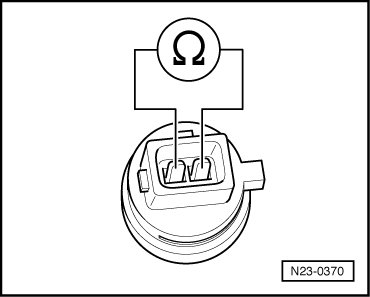
Range A displays resistance values for the temperature range of 0 to 50 °C, range B displays resistance values for the temperature range of 50 to 100 °C.
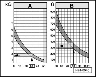
Example:
• 30°C is in range A and corresponds to a resistance of 1.5 to 2.0 kohms
• 80°C is in range B and corresponds to a resistance of 275 to 375ohms
If specification is not obtained:
- Replace Engine Coolant Temperature (ECT) Sensor (G62).
CAUTION!
• Cooling system is under pressure.
• Danger of scalding when opening!
- Erase DTC memory of Engine Control Module => [ Diagnostic Mode 04 - Erase DTC Memory ] Diagnostic Modes 01 - 09, Diagnostic mode 4: Reset/erase diagnostic data.
- Generate readiness code => [ Readiness Code, Generating ] Monitors, Trips, Drive Cycles and Readiness Codes.
If no malfunctions are detected in the wires and the resistance values are OK:
If no malfunction is detected in the wiring, replace the engine control module.