Coolant Fan Control Modules, Checking
Diagnostic Procedures
Coolant Fan Control Modules, Checking
Special tools, testers and auxiliary items required
• Hand multimeter (V.A.G 1526) or Multimeter (V.A.G 1715)
• Test adapter kit (V.A.G 1594)
• Wiring diagram
Test conditions
• Battery voltage (both batteries) must be at least 11.5 Volts.
• All electrical consumers such as, lights and rear window defroster must be switched off.
• For vehicles with automatic transmission, selector lever must be in " P".
• Parking brake must be engaged.
• The Ground (GND) connections between engine and body must be OK.
• Ignition switched off.
• Motronic Engine Control Module (ECM) Power Supply Relay 2 (J670) must be OK, checking:
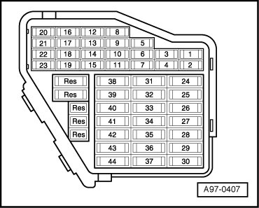
• Fuses in right instrument panel fuse holder must be OK:
Right instrument panel fuse holder
Test Sequence
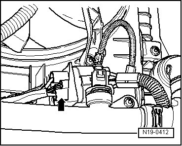
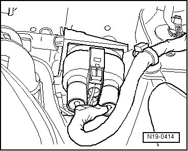
- Disconnect corresponding 4-pin harness connector from Coolant Fan Control (FC) Control Module (J293):
• 4-pin connector - arrow - from Coolant Fan Control (FC) Control Module (J293)
• 4-pin connector from Coolant Fan Control (FC) Control Module 2 (J671)
Checking voltage supply
- Connect multimeter to terminals 1 + 4 and 2 + 4 of connector to Engine Control Module (ECM) for voltage measurement.
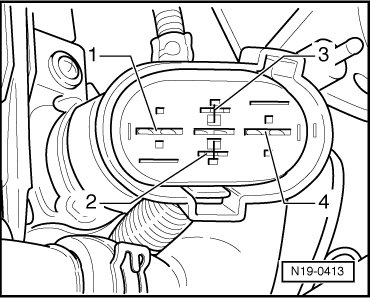
- Switch ignition on. Specification: at least 10.0 V
- Switch ignition off.
If no voltage is present:
- Check wiring between 4-pin connector (terminals 1 and 2) and corresponding fuses in right instrument panel fuse holder for short circuit according to wiring diagram. Wiring resistance: max. 1.5 ohms
Right instrument panel fuse holder
- Check for open circuit in wire between 4-pin connector terminal 4 and Ground (GND) according to wiring diagram. Wiring resistance: max. 1.5 ohms
- Erase DTC memory of Engine Control Module => [ Diagnostic Mode 04 - Erase DTC Memory ] Diagnostic Modes 01 - 09, Diagnostic mode 4: Reset/erase diagnostic data.
- Generate readiness code => [ Readiness Code, Generating ] Monitors, Trips, Drive Cycles and Readiness Codes.
If there is no malfunction in the voltage supply:
- Check wire to Engine Control Module according to wiring diagram.
Checking wire to Engine Control Module (ECM)
- Connect test box to Engine Control Module (ECM) (J623) wiring harness on connecting test box for wiring test, refer to Repair Manual,
- Check wire between test box and 4-pin connector to Engine Control Module (ECM) for open circuit according to wiring diagram. Wiring resistance: max. 1.5 ohms

- Check wire for short circuit to vehicle Ground (GND) and to B+. Specification: infinite ohms
- Erase DTC memory of Engine Control Module => [ Diagnostic Mode 04 - Erase DTC Memory ] Diagnostic Modes 01 - 09, Diagnostic mode 4: Reset/erase diagnostic data.
- Generate readiness code => [ Readiness Code, Generating ] Monitors, Trips, Drive Cycles and Readiness Codes.
If no malfunction is found in the wire and there was voltage between terminals 1 + 4 and 2 + 4:
- Replace corresponding Coolant Fan Control Module:
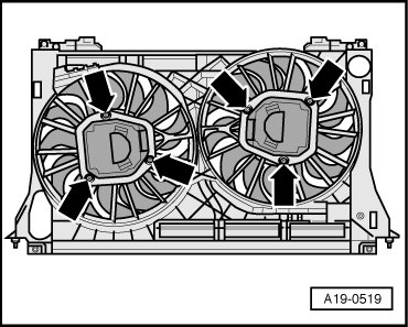
• Coolant Fan Control (FC) Control Module 2 (J293) - 5 - with Coolant Fan (V7) - 4 -
• Coolant Fan Control (FC) Control Module 2 (J671) - 1 - with Coolant Fan 2 (V177) - 2 -
- Erase DTC memory of Engine Control Module => [ Diagnostic Mode 04 - Erase DTC Memory ] Diagnostic Modes 01 - 09, Diagnostic mode 4: Reset/erase diagnostic data.
- Generate readiness code => [ Readiness Code, Generating ] Monitors, Trips, Drive Cycles and Readiness Codes.