Component Locations Overview
Component Locations
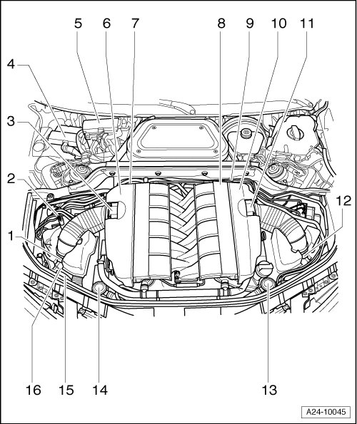
Components A through E are not shown in the exploded view illustration.
A - Brake light switch (-F-) and Brake pedal switch (-F47-)
• In footwell at brake pedal
B - Data Link Connector
• Located in knee bolster on driver's side
C - Throttle position (TP) sensor (-G79-) and Sender 2 for accelerator pedal position (-G185-)
• In footwell on accelerator pedal (both sensors are integrated into one housing)
D - "MIL" Warning lamp
• In instrument cluster
E - "EPC" Warning lamp
• In instrument cluster
1 - Mass Air Flow (MAF) sensor 2 (-G246-) with Intake Air Temperature (IAT) sensor 2 (-G299-)
• For cylinder bank 2 (cylinders 7 to 12)
• Removing and installing => [ Installing ] Mass Air Flow Sensor 2
• The intake channels cross in the center of the intake manifold. The Mass Air Flow (MAF) sensor 2 (-G246-) on the right side (as seen in driving direction) therefore measures the intake air mass for cylinder bank 2 on the left side (as seen in driving direction). The same applies to the Intake Air Temperature (IAT) sensor 2 -G299-.
2 - Electrical connections for oxygen sensors
3 - Throttle valve control module 2 (-J544-)
• with Throttle drive 2 (power accelerator actuation) (-G296-), Angle sensor 1 (on throttle drive 2 power accelerator actuation) (-G297-) and Angle sensor 2 (on throttle drive 2 power accelerator actuation) (-G298-)
• For cylinder bank 2 (cylinders 7 to 12)
• Pay attention to first phrase in above mentioned note
4 - Engine Control Module (ECM) 2 (-J624-)
• In Electronics box in plenum chamber
• Mark before disconnecting, to prevent switching with Engine Control Module (ECM) 1
5 - Engine Control Module (ECM) (-J623-)
• In Electronics box in plenum chamber
• Mark before disconnecting, to prevent switching with Engine Control Module (ECM) 2
6 - Camshaft Position (CMP) sensor 3 (-G300-)
• For exhaust camshaft
• Cylinder bank 1
7 - Camshaft Position (CMP) sensor 2 (-G163-)
• For intake camshaft
• Cylinder bank 2
8 - Camshaft Position (CMP) sensor (-G40-)
• For intake camshaft
• Cylinder bank 1
9 - Engine speed (RPM) sensor (-G28-)
10 - Camshaft Position (CMP) sensor 4 (-G301-)
• For exhaust camshaft
• Cylinder bank 2
11 - Throttle valve control module (-J338-)
• with Throttle drive (power accelerator actuation) (-G186-), Angle sensor 1 for throttle drive (power accelerator actuation) (-G187-) and Angle sensor 2 for throttle drive (power accelerator actuation) (-G188-)
• For cylinder bank 1 (cylinders 1 to 6)
12 - Mass Air Flow (MAF) sensor (-G70-) with Intake Air Temperature (IAT) sensor (-G42-)
• For cylinder bank 1 (cylinders 1 to 6)
• Removing and installing => [ Removing ] Mass Air Flow Sensor 2
• The intake channels cross in the center of the intake manifold. The Mass Air Flow (MAF) sensor (-G70-) on the left side (as seen in driving direction) therefore measures the intake air mass for cylinder bank 1 on the right side (as seen in driving direction). The same applies to the Intake Air Temperature (IAT) sensor (-G42-).
13 - Mechanical EGR valve
14 - Mechanical EGR valve
15 - Secondary Air Injection (AIR) pump motor 2 (-V189-)
• For cylinder bank 2
• In lower part of air filter housing
16 - Secondary Air Injection (AIR) pump motor (-V101-)
• For cylinder bank 1
• In lower part of air filter housing
Oxygen sensor connector
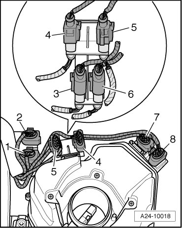
1 - Connector for Heated Oxygen Sensor (HO2S) 3 (-G285-), before catalytic converter
• Exhaust bank 3 (cylinder 7, 8, 9)
• 6-pin, black
2 - Connector for Heated Oxygen Sensor (HO2S) 4 (-G286-), before catalytic converter
• Exhaust bank 4 (cylinder 10, 11, 12)
• 6-pin, brown
3 - Connector for Oxygen Sensor (O2S) 3 Behind Three Way Catalytic Converter (TWC) (-G287-)
• Exhaust bank 3 (cylinder 7, 8, 9)
• 4-pin, green
4 - Connector for Oxygen Sensor (O2S) Behind Three Way Catalytic Converter (TWC) (-G130-).
• Exhaust bank 1 (cylinder 1, 2, 3)
• 4-pin, black
5 - Connector for Oxygen Sensor (O2S) 2 Behind Three Way Catalytic Converter (TWC) (-G131-).
• Exhaust bank 2 (cylinder 4, 5, 6)
• 4-pin, brown
6 - Connector for Oxygen Sensor (O2S) 4 Behind Three Way Catalytic Converter (TWC) (-G288-)
• Exhaust bank 4 (cylinder 10, 11, 12)
• 4-pin, gray
7 - Connector for Heated Oxygen Sensor (HO2S) 2 (-G108-), before catalytic converter
• Exhaust bank 2 (cylinder 4, 5, 6)
• 6-pin, brown
8 - Connector for Heated Oxygen Sensor (HO2S) (-G39-), before catalytic converter
• Exhaust bank 1 (cylinder 1, 2, 3)
• 6-pin, black
• For this overview, the intake manifold is removed.
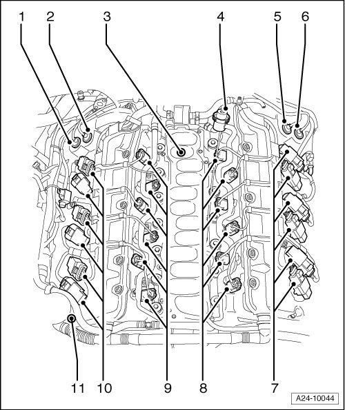
1 - Camshaft adjustment valve 1 (exhaust) (-N318-)
2 - Valve 1 for camshaft adjustment (-N205-) Intake
3 - Map controlled engine cooling thermostat (-F265-)
4 - Fuel pressure regulator
5 - Valve 2 for camshaft adjustment (-N208-)
6 - Camshaft adjustment valve 2 (exhaust) (-N319-)
7 - Ignition coils with power output stages, Cylinder bank 2
• Ignition Coil 7 with Power Output Stage (-N325-)
• Ignition Coil 8 with Power Output Stage (-N326-)
• Ignition Coil 9 with Power Output Stage (-N327-)
• Ignition Coil 10 with Power Output Stage (-N328-)
• Ignition Coil 11 with Power Output Stage (-N329-)
• Ignition Coil 12 with Power Output Stage (-N330-)
• The number of each cylinder is stamped into the valve cover.
8 - Fuel injectors, Cylinder bank 2
• Cylinder 7 Fuel Injector (-N85-)
• Cylinder 8 Fuel Injector (-N86-)
• Cylinder 9 Fuel Injector (-N299-)
• Cylinder 10 Fuel Injector (-N300-)
• Cylinder 11 Fuel Injector (-N301-)
• Cylinder 12 Fuel Injector (-N302-)
• The number of each cylinder is stamped into the valve cover.
9 - Fuel injectors, Cylinder bank 1
• Cylinder 1 Fuel Injector (-N30-)
• Cylinder 2 Fuel Injector (-N31-)
• Cylinder 3 Fuel Injector (-N32-)
• Cylinder 4 Fuel Injector (-N33-)
• Cylinder 5 Fuel Injector (-N83-)
• Cylinder 6 Fuel Injector (-N84-)
10 - Ignition coils with power output stages, Cylinder bank 1
• Ignition Coil 1 with Power Output Stage (-N70-)
• Ignition Coil 2 with Power Output Stage (-N127-)
• Ignition Coil 3 with Power Output Stage (-N291-)
• Ignition Coil 4 with Power Output Stage (-N292-)
• Ignition Coil 5 with Power Output Stage (-N323-)
• Ignition Coil 6 with Power Output Stage (-N324-)
11 - Right Electro-hydraulic engine mount solenoid valve (-N145-)
• The oxygen sensors, exhaust manifold and primary catalytic converter are shown below.
• The engine is equipped with a total of eight oxygen sensors.
• To keep the illustration simple, the crankcase and cylinders (number 1 to 12) are only shown in schematic form.
• The oxygen sensors, exhaust manifolds and primary catalytic converter are, however, shown as they are installed in the vehicle.
• Arrow points in direction of travel.
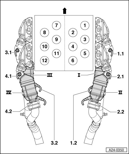
I - Primary catalytic converter for cylinders 1, 2, 3; also referred to as -exhaust bank 1-.
II - Primary catalytic converter for cylinders 4, 5, 6; also referred to as -exhaust bank 2-.
III - Primary catalytic converter for cylinders 7, 8, 9; also referred to as -exhaust bank 3-.
IV - Primary catalytic converter for cylinders 10, 11, 12; also referred to as -exhaust bank 4-.
1.1 - Heated Oxygen Sensor (HO2S) (-G39-) with oxygen sensor heater; before catalytic converter
• Exhaust bank 1 (cylinder 1, 2, 3)
1.2 - Oxygen Sensor (O2S) Behind Three Way Catalytic Converter (TWC) (-G130-) with oxygen sensor heater
• Exhaust bank 1 (cylinder 1, 2, 3)
2.1 - Heated Oxygen Sensor (HO2S) 2 (-G108-) with oxygen sensor heater; before catalytic converter
• Exhaust bank 2 (cylinder 4, 5, 6)
2.2 - Oxygen Sensor (O2S) 2 Behind Three Way Catalytic Converter (TWC) (-G131-) with oxygen sensor heater
• Exhaust bank 2 (cylinder 4, 5, 6)
3.1 - Heated Oxygen Sensor (HO2S) 3 (-G285-) with oxygen sensor heater; before catalytic converter
• Exhaust bank 3 (cylinder 7, 8, 9)
3.2 - Oxygen Sensor (O2S) 3 Behind Three Way Catalytic Converter (TWC) (-G287-) with oxygen sensor heater
• Exhaust bank 3 (cylinder 7, 8, 9)
4.1 - Heated Oxygen Sensor (HO2S) 4 (-G286-) with oxygen sensor heater; before catalytic converter
• Exhaust bank 4 (cylinder 10, 11, 12)
4.2 - Oxygen Sensor (O2S) 4 Behind Three Way Catalytic Converter (TWC) (-G288-) with oxygen sensor heater; after catalytic converter
• Exhaust bank 4 (cylinder 10, 11, 12)
• In the following illustration, the component locations of the knock sensors are only shown in schematic form.
• The knock sensors are located on the outer sides of the crankcase, not in the "V" as e.g. on the bi-turbo engine.
• The engine is equipped with a total of four knock sensors.
• Arrow points in direction of travel.
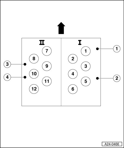
I - Cylinder bank 1 (cylinders 1 to 6)
II - Cylinder bank 2 (cylinders 7 to 12)
1 - Knock sensor 1 (-G61-)
• Knock sensor 1 detects engine knocks in cylinders 1, 2 and 3.
2 - Knock sensor 2 (-G66-)
• Knock sensor 2 detects engine knocks in cylinders 4, 5 and 6.
3 - Knock sensor 3 (-G198-)
• Knock sensor 3 detects engine knocks in cylinders 7, 8 and 9.
4 - Knock sensor 4 (-G199-)
• Knock sensor 4 detects engine knocks in cylinders 10, 11 and 12.