Knock Sensor: Testing and Inspection
Diagnostic Procedures
Knock Sensors, Checking
• Contact surfaces between knock sensor and cylinder block must be free of corrosion, dirt and grease.
• To ensure problem-free function of knock sensors, it is important that torque specification of 20 Nm be adhered to exactly.
• Use only gold-plated terminals when servicing terminals in harness connector of knock sensors.
Special tools, testers and auxiliary items required
• Hand multimeter (V.A.G 1526) or Multimeter (V.A.G 1715)
• Test adapter kit (V.A.G 1594)
• Wiring diagram
Test Conditions
• The Ground (GND) connections between engine and body must be OK.
• Knock sensor screws tightened to 20 Nm.
• Ignition switched off.
Test Sequence
Cylinder bank 1
- Disconnect corresponding 3-pin harness connector from Knock Sensor (KS):
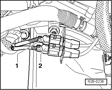
1 Knock Sensor (KS) 1 (G61)
Color identification: white
f For exhaust bank 1 of cylinders 1, 2 and 3
2 Knock Sensor (KS) 2 (G66)
Color identification: Gray
f For exhaust bank 2 of cylinders 4, 5 and 6
• The 3-pin harness connectors are located above torque converter housing and are only accessible after lowering the subassembly.
Cylinder bank 2
- Disconnect corresponding 3-pin harness connector from Knock Sensor (KS):
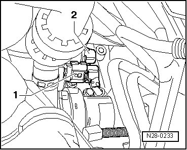
1 Knock Sensor 3 (G198)
Color identification: brown
f For exhaust bank 3 of cylinders 7, 8 and 9
2 Knock sensor 4 (G199)
Color identification: black
f For exhaust bank 4 of cylinders 10, 11 and 12
Cylinder bank 1 and 2
• Before disconnecting harness connectors, mark allocation to component.
• Cylinder bank 1 with cylinders 1 through 6 is located at right in direction of travel.
• Cylinder bank 2 with cylinders 7 through 12 is located at left in direction of travel.
Checking resistances
- Check resistance between terminals 1 + 2, 1 + 3 and 2 + 3 at the connections to the respective knock sensors. Specification: infinite ohms
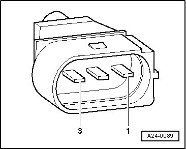
If specification is not obtained:
- Replace respective knock sensor:
• Knock sensors 1 and 2 for cylinder bank 1
• Knock sensors 3 and 4 for cylinder bank 2.
- Erase DTC memory of Engine Control Module => [ Diagnostic Mode 04 - Erase DTC Memory ] Diagnostic Modes 01 - 09, Diagnostic mode 4: Reset/erase diagnostic data.
- Generate readiness code => [ Readiness Code, Generating ] Monitors, Trips, Drive Cycles and Readiness Codes.
If specification is obtained:
- Check wires to Engine Control Module according to wiring diagram.
Checking wires to Engine Control Module 1
Cylinder bank 1
- Connect test box to Engine Control Module (ECM) (J623) wiring harness on connecting test box for wiring test.
Cylinder bank 2
- Connect test box to Engine Control Module (ECM) 2 (J624) wiring harness on connecting test box for wiring test.
Cylinder bank 1 and 2
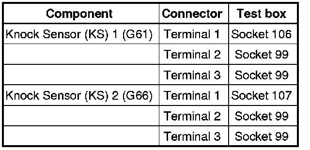
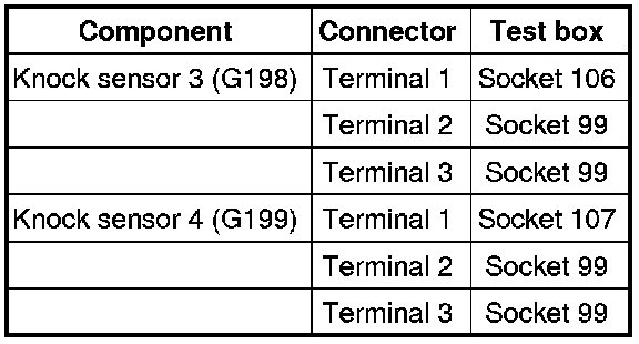
- Check wires between test box and 3-pin connector to Engine Control Module (ECM) for open circuit according to wiring diagram. Wiring resistance: max. 1.5 ohms
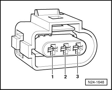
Cylinder bank 1
Cylinder bank 2
Cylinder bank 1 and 2
- Check wires for short circuit to each other. Terminal 1 + Socket 99 specified value: infinite ohms
- Erase DTC memory of Engine Control Module(ECM) => [ Diagnostic Mode 04 - Erase DTC Memory ] Diagnostic Modes 01 - 09, Diagnostic mode 4: Reset/erase diagnostic data.
- Generate readiness code => [ Readiness Code, Generating ] Monitors, Trips, Drive Cycles and Readiness Codes.
If no malfunction is detected in the wiring:
Cylinder bank 1
- Replace Engine Control Module (ECM) (J623).
Cylinder bank 2
- Replace Engine Control Module (ECM) 2 (J624).