Secondary Air Injection Pump Motor, Checking
Diagnostic Procedures
Secondary Air Injection Pump Motor, Checking
Special tools, testers and auxiliary items required
• Multimeter.
• Wiring diagram.
Test requirements
• The Secondary Air Injection (AIR) Pump Relay (-J299-) OK.
• The Motronic Engine Control Module (ECM) Power Supply Relay (J271) OK.
• Battery voltage at least 12.5 V.
• All electrical consumers switched off (radiator fan must NOT run during test).
• A/C switched off.
• The ignition switched off.
Procedure
Procedure
- Raise the vehicle.
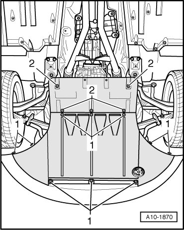
- Loosen the quick release fasteners - 1 - and - 2 - and remove the noise insulation panel.
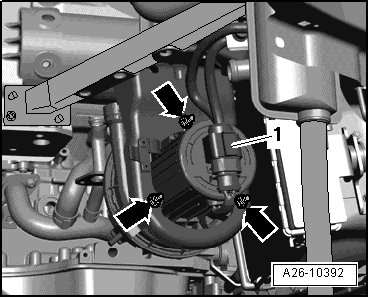
- Disconnect the Secondary Air Injection (AIR) Pump Motor (-V101-) electrical harness connector - 1 -.
Checking voltage
- Crank the engine.
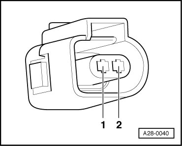
- Using a Multimeter, check the Secondary Air Injection (AIR) Pump Motor (-V101-) electrical harness connector terminals 1 to 2 for voltage.
- Switch the ignition off.
Specified value: battery voltage.
If the specified value was not obtained:
- Using a Multimeter, check the Secondary Air Injection (AIR) Pump Motor (-V101-) electrical harness connector terminal 2 to Ground (GND).
Specified value: battery voltage.
If the specified value was not obtained:
- Check the wiring connection from the Secondary Air Injection (AIR) Pump Relay (-J299-) socket 8/87 to the Secondary Air Injection (AIR) Pump Motor (-V101-) electrical harness connector terminal 2 for an open circuit or a short circuit.
- Check the wiring connections for damage, corrosion, lose or broken terminals.
- If necessary, repair the faulty wiring connection.
If the specified value was obtained:
Checking Ground (GND)
- Using a Multimeter, check the Secondary Air Injection (AIR) Pump Motor (-V101-) electrical harness connector terminal 1 to Ground (GND) for resistance.
Specified value: 1.5 ohms Max.
If the specification was not obtained:
- Check the wiring for a short circuit to each other, Battery (+), and Ground (GND).
- Check the electrical harness connector for damage, corrosion, lose or broken terminals.
- If necessary, repair the faulty wiring connection.
If no malfunction is found in the wiring and voltage supply was OK:
- Replace the Secondary Air Injection (AIR) Pump Motor (-V101-).
- Assembly is performed in the reverse order of removal.
Final procedures
After repair work, the following work steps must be performed in the following sequence:
1. Check the DTC memory. Refer to => [ Diagnostic Mode 03 - Read DTC Memory ] Diagnostic Modes 01 - 09.
2. If necessary, erase the DTC memory. Refer to => [ Diagnostic Mode 04 - Erase DTC Memory ] Diagnostic Modes 01 - 09.
3. If the DTC memory was erased, generate readiness code. Refer to => [ Readiness Code ] Monitors, Trips, Drive Cycles and Readiness Codes.
- End of diagnosis.